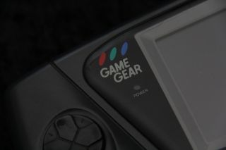
The Game Gear has a smaller screen than the master system... rather strangely it actually has a better colour palette! but appart from that, they are identical, and can run the same basic games!
Lets take a look at the specs!


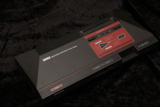
| Unlike the Gameboy, the SMS and GG
have a real Z80 CPU!... Quite surprisingly the Master System and
Game Gear are pretty much the same system... it was also known as
the Sega Mark III in Japan. The Game Gear has a smaller screen than the master system... rather strangely it actually has a better colour palette! but appart from that, they are identical, and can run the same basic games! Lets take a look at the specs! |
|
|
|
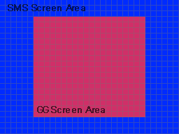
The smaller screen is handled by 'skipping the 6 tiles from the left and right side, and 3 from the top and bottom... So we can write a game for our gamegear, and run it on a mastersystem, we just need to design around the screen size difference, and use some different palette code! |
  |
ChibiAkumas Tutorials
Console graphics hardware - Tiles and Sprites!
This section is a general description, and not SMS/GG specific, skip to the next chapter if you know the concept of tiles and sprite layers!| The Gameboy,Gamegear and Mastersystem
screens do not work like they do on computers like the CPC Graphics are not just 'bytes' in a memory address... The screen is made up of a 'Tile Layer' and a 'Sprite Layer' To explain Tiles and sprites, lets look at our imaginary game shown to the right 'The Super Yuusha Siblings', on a theoretical game system the 'GameChibi'... Just to be very clear, we looking at this as a concept, not the actual layout of the gameboy! Looking at our example, We have a level with some grass, blocks, and some collectable 'stars'... our hero, Yume is controlled by the player... |
|
| The screen is made up of the Tile
layer, and the Sprite Layer, Usually Sprites are drawn above the Tiles... but sometimes they may be drawn below. It's also possible we could use sprites for the stars.. but sprites are very limited, so the object doesn't move, then tiles will do the job... we can even animate the stars by switching the tile between different patterns |
|
| The tile array on the systems we'll
be looking at is made up of 8x8 tiles... the array is a 'grid' of
these tiles, so the tiles must line up, a block cannot be at a 'half
way boundary' Tiles are defined by a number (usually 0-255)... we define the bitmap (image) data for that tile (we'll call it a pattern), then tell the hardware what positions in the tile array to use that pattern. In our example, the black background is pattern 0 ... the blocks are pattern 1... the grass is pattern 2... and the stars are pattern 3 Our 'GameChibi' console has a tile array of 8x8... and 64 bytes is used to define the tile grid... So to define the stars, we need to set memory locations 10,20 and 15 of the tile array to byte '3' A real system usually has a tile array bigger than the screen (maybe just by one row and one coumn)... this is to allow smooth scrolling of the screen, where two tiles are 'half shown' Now in the case of our 'GameChibi' system, with it's 64 tile screen, and 256 pattern definitions, we could just set every visible tile to a different pattern, and treat the screen as a plain bitmap again... We can do that on the MSX1, but unfortunately the Gameboy and Mastersystem have too few tiles for their screen size, so some parts of the screen must contain the same tile! |
| Because our system is using hardware sprites, we have to design
our game sprites in a way that can be drawn with the hardware
sprites... for example lets look at our Yume sprite... if our
'GameChibi' used 8x8 hardware sprites, we would have to use 48 of
them to make this image!... we can save 5 (marked green)... these
have no data, so we can just not draw them... When it comes to moving our character, the software will have to move the hardware sprites all together, so the user does not realise they are made up of many sprites!... on systems with more onscreen colors than sprite colors, two or more sprites may be overlapped to make the sprite appear more colorful Most systems will have one color (usually 0) which marks the transparent colour. but there is a problem! with software sprites on a bitmap screen, we can draw as much as we want, it will just get slow.... but with hardware sprites, we have a fixed limit of how many sprites can be shown onscreen at once! sounds bad? well actually it's worse, even though a system like the master system can show 64 sprites onscreen, there can only be 8 on a line... if more than 10 appear on the same line, some will flicker, or not appear... there's nothing we can do about it, we just have to design our game to avoid this problem! |
| The Sega Mastersystem and Sega game gear are almost the same
system, the major difference is the screen size, The SMS screen is
256x192, but the GG screen is 160x144... If we draw the same data to the screen, we'll realize that the gamegear is drawing only the center area of the SMS screen area, with 3 lines missing from the top and bottom, and 6 columns missing from the left and right sides. While both systems are 16 color, The Gamegear has a better color palette! The MasterSystem uses a single byte palette in the format: --BBGGRR The GameGear uses 2 bytes, in the format ----BBBB GGGGRRRR |
 |
| The Gamegear rom is pretty simple,
when the console starts, execution begins at memory address
&0000, The 'Header' which defines the cartridge is 16 bytes, and typically appears at &7FF0 some of the attributes are not a full byte, and use half a byte (a nibble) if you're using an emulator, you do not need need a header! even without the 'System type' the 'Fusion' emulator will use the file extension (SMS or GG) to detect the system to use. if the system is a Majesco SGG the �TMR SEGA� bytes must be present (Checksum is ignored)... if it's not the screen will be black If the system is an Export SMS the checksum must be correct - if it's not you will get the message "Software Error" My 'BinaryTools' program can build a valid file with the following command: BinaryTools.exe checksum "\RelSMS\cart.sms" $0000 $7FF0 "\RelSMS\cart.sms" $7FFA 16bit |
|
| Note, some of these ports also respond to alternate addresses, so you may see different port numbers in other programs. |
|
| Vram is separate so must be accessed by OUT commands on the SMS/GG... Note, Palette data is addressed using &C000... however this is actually not a memory address in the VDP, as the VDP only has 16k ram. |
|
| The GameGear and Mastersystem use 2x
16 color palettes... Background Tiles can use either of the 2 palettes... sprites always use the second one. The Mastersystem uses just 2 bits per color channel... meaning 1 byte per definition The GameGear uses 1 nibble per channel.. meaning 2 bytes per definition... this means the memory locations are different on the SMS and GG SMS Palette Definition:
GG Palette Definition:
|
|
Gamegear & Mastersystem Tilemap
The 2 bytes that define each tile are in the format ---PCVHN NNNNNNNN
| Bit | Function |
| - | no function |
| P | Priority (1=Tile in front of Sprites... 0=behind) |
| C | Color palette (0=normal 1=Sprite palette) |
| V | Vertical Flip (1=on) |
| H | Horizontal flip (1=on) |
| NNNNNNNNN | Tile number (0-511) |
| The SMS/GG memory supports up to 64
sprites, they can be 8x8 or 8x16 pixels. They use the second palette of 16 colors. if you don't set the palette, all your sprites will be black! It is not possible to X or Y flip sprites. There are 3 memory bytes for each hardware sprite, but they are not consecutive! Look at sprite 0... it's Y co-ordinate is at &3F00 ... it's X co-ordinate is at &3F80... it's Sprite Number is at &3F81 Sprite Numbers can come from memory address &2000 (Tile 256+), or &0000 (Tile 0-255) depending on the setting of register &06 |
To Set
a register we out the value to the control port, then the register number
+128.
For Example: lets set register 8 to value 11
| Register Number | Purpose | Bits | Bit meaning |
| &00 | Mode Control No. 1 | VHLISMXs |
V=Lock Right 8 columns, H=Lock Top 16 pixels... L=hide left
8 pixes |
| &01 | Mode Control No. 2 | -EF13-LD |
E=Enable screen / F=Frame interrupt / 13 = Mode bits / L=Large
16x8 Sprites size / D=Double size sprites |
| &02 | Name Table Base Address | ----NNNM |
&FF = TileMap at &3800 &FD = TileMap at &3000 |
| &03 | Color Table Base Address | 11111111 |
|
| &04 | Pattern Generator Table Base Address | PPPPP11 |
|
| &05 | Sprite Attribute Table Base Address | -----SMM | |
| &06 | Sprite Pattern Generator Table Base Address | - - - - - S - - | S=Sprite Table Address (0= use patterns for sprites, 1=sprites at &2000) |
| &07 | Overscan/Backdrop Color | ||
| &08 | Background X Scroll | T T T T T P P P | T = Tile offset (0-31), P=Pixel offset |
| &09 | Background Y Scroll | T T T T T P P P | T = Tile offset (0-27), P=Pixel offset |
| &0A | Line counter |
| The GameGear and Master System use 3
ports in total, but there are differences! The Gamegear has an extra button! 'Start' accessible from bit 7 of Port &00... The Gamegear does not have any player 2 controls The Mastersystem has no start button, but it does have a second player paddle! The 'Pause button' on the console causes a NMI call to address & note:Button TH has no use on the normal SMS gamepads, so is not used in these examples. |
|
|
|
| Bits | |||||||||
| Command | Bit Details | 7 | 6 | 5 | 4 | 3 | 2 | 1 | 0 |
| Format Template | L=Latch C=Channel T=Type XXXX=Data | L | C | C | T | D | D | D | D |
| Tone - Command 1/2 | C=Channel L=tone Low data | 1 | C | C | 0 | L | L | L | L |
| Tone - Command 2/2 | H= High tone data (Higher numbers = lower tone) | 0 | - | H | H | H | H | H | H |
| Volume | C=Channel (0-2) V=Volume (15=silent 0=max) | 1 | C | C | 1 | V | V | V | V |
| Noise Channel | (Channel 3) M=Noise mode (1=white) R=Rate (3=use tone 2) | 1 | 1 | 1 | 0 | - | M | R | R |
My SMS/GG site - A breif overview of the system, I'll be including these systems in my tutorials soon!