<-
Back to the Main Contents & Basic Z80 Assembly Lessons
Introduction to the Advanced Series...
The Advanced series continues where the beginner series left
off!... These lessons will teach you how to do things with the Z80 that
are really essential for programming... Though you won't need them to get
started with Z80... and may never need them at all, if you want to know
everything there is about the Z80, and how best to use it, then these are
some things you'll want to know!
These lessons aren't related to a particular computer, but the Z80 itself,
so we'll be doing all our testing and practice with WinApe again!
Lesson
A1 - Binary Coded Decimal
We've looked at HEX, and DECIMAL before, but there's one 'weird'
way of storing data that - while not as efficient with memory -
will let us store super-large numbers, and show them easily to the
screen!... and that's Binary Coded Decimal! |
 |
 |
 |
 |
 |
Binary Coded
Decimal is Super-Simple... rather than storing 0-255 in a
byte... we just store 0-9! Why do we want to do that? well
converting numbers stored in HEX to ascii for the screen can be
a real pain! but Binary Coded Decimal makes it easy... lets take
a look! |
Lets see how BCD compares to decimal and hex...
| Number |
1234 |
| Hex |
&04D2 |
| Binary Coded Decimal |
&01 &02 &03 &04 |
| Packed Binary Coded
Decimal |
&12 &34 |
So with
Binary Coded
Decimal all we've done, is stored each digit in a byte of its
own, that will make showing the numbers to screen really easy, and if we
want 100 digits(!) we'd just use 100 bytes!
Packed Binary Coded
Decimal is an alternate form, we use both nibbles of the byte to
represent our numbers, so we only need 50 bytes for 100 digits... but in
either case A-F have no meaning, so if a BCD byte contains &1F...
something has gone wrong!... The Z80 works best with packed BCD... so
that's what we're going to use!
 |
In the
example above, the most significant byte was stored first, so
1345678 would be stored &12 &34 &56 &78... in
this lessons examples we're going to store things backwards, so
it would be stored &78 &56 &34 &12.... this is
because many of our commands will start from the least
significant byte, so we can save a little time this way!... if
you don't like it, you can always change the code! |
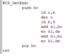
Starting from the Most Significant Byte
Some of our commands WILL need to
start from the end of the data... so we're going to create a
simple function to alter HL and DE to move to the end of a BCD
number B bytes in length...
Our BCD commands are going to store the number of bytes in B... so
to get HL and DE to point to the last byte, we need to add B-1
We're doing this to HL and DE because most of our commands use two
parameters |
 |
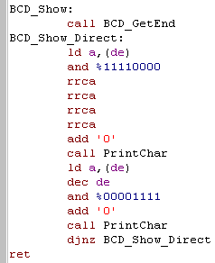
Showing BCD
Showing BCD is easy!
First we need to move to the highest value byte... then we convert
the top nibble to Ascii - and show it!
Then we do the same for the Bottom nibble... and show that as
Ascii too!
We then repeat until B is Zero, to show all the bytes...
Much easier and faster than if we were storing HEX!
|
 |
How DAA Works...
The only difference between BCD and HEX is that we're not using
A-F... so all we need to do is change accumulator if either nibble changes
to an A-F... and handle Carrying bits to the next BCD byte... and that's
what DAA does!
It basically solves all our BCD problems in one command!... lets take a
look!
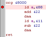
Try the program to the right! Put a
breakpoint on the first command, and watch how DAA alters A and
the Carry flag to keep things right!
DAA also uses the H Flag for its own purposes... but that's not
something we need to worry about!
Basically, We can do ADD/ADC or SUB/SBC on a byte.. and DAA will
fix things... we just need to alter the next byte if the carry
flag is set! |
 |
Ok,
so
we've shown some numbers to the screen, but we actually need to
be able to do some maths too!... fortunately the Z80 allows us
to use our typical ADC and SBC commands to do addition and
subtraction in Binary Coded Decimal! How? well its simple
actually!
|
 |
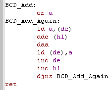
BCD Addition
Now we know how to use DAA things
aer pretty easy...
Lets create a function that adds BCD value at (HL) to the one at
(DE)... for B bytes
We do OR A to clear the carry flag... then we process each
byte (from smallest to biggest) using ADC to add the values...
DAA sorts out our numbers, and we store the result, then we just
repeat... ADC will add the carry if there was one caused by the
last addition |
 |
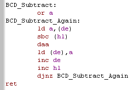
BCD Subtraction
| Subtraction is basically exactly
the same, we just use SBC this time instead! |
 |
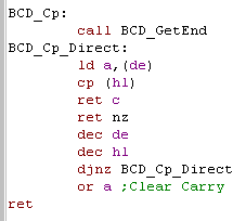
BCD Compare
Finally, we may want to compare a
BCD value to another, and see if they are equal, or which is
higher...
If we start from the most significant byte, we can just do our CP
to compare, returning as soon as we find a byte that is different.
If both are the same, we just clear the carry flag and return Z |
 |
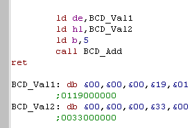
Usage!
Ok, We're done!
All the commands today are run in the same way, by passing the
address of one or usually two parameters in HL and DE, and
the length in B,
Remember, the BCD data is in reverse order!
If you want to see more, take a look at "Lesson_A1.asm" in the
Samples.7z! |
 |
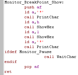
Monitor_BreakPoint_Show:
This is not called by the user
directly, it's called by the other modules and shows HL as hex,
surrounded by ** symbols
If needed it will pause the system after showing the Breakpoint or
register |
 |
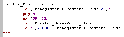
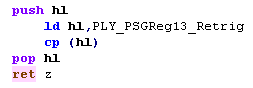
Monitor_PushedRegister:
This module will pop a register and show it to screen... because
we need HL, but don't want to use the stack we back it up with
self modifying code...
Then we pop a pair of the stack... this will be the return
address... Next we swap HL with the pair on the stack... HL will
now be the pair pushed before the call, and the return address
will be at the top of the stack...
All that's left to do is show HL... then restore HL and
return to our program! |
 |
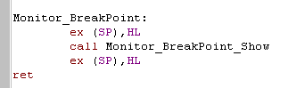
Monitor_BreakPoint:
| This module is super simple! all it
does is get the return address off the stack.. show it, and
return! |
 |
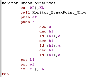
Monitor_BreakPointOnce:
More complex than the last
version... this one overwrites the 3 bytes preceeding the return
address...
These will be the CALL command that called the monitor - the end
result is that the monitor is only called once... so it can
be used in a repeating loop to find out the program counter
location (or if the loop even ran - if your program is crashing)
without slowing down the program with lots of pauses. |
 |
Lesson
A2 - Interrupt Mode 2
We've looked at Interrupt mode 1 before in Lesson
7 ,but there's more stuff we need to cover before we've
mastered them!
Lets take another look now, quickly at Interrupt Mode 0 (which is
useless) Mode 1 again, and then we'll look at how to make use of
the less used Interrupt Mode 2, and why it may really help you!
|
|
|
|
|
What is an Interrupt?
An interrupt occurs when a device connected to the Z80 demands it's
attention! In practical terms, this is happens when the screen has redrawn
(50 hz) or at multiple times during a redraw (depending on hardware and
configuration) - because the calling devices matters... there's no one
rule for all Z80 systems!
Why do we use interrupts?
We use interrupts to precisely time things, to make our music play at the
right time, or to detect when the screen is redrawing a certain line - if
we're messing with colors, or trying to make our limited hardware sprites
appear more often than they should!
Interrupt Mode 0
There's not any use I know of for IM0 - in this mode, the device which
causes the interrupt forces the Z80 to immediately call a 1 byte command
(usually an RST - as they are all 1 byte commands)
Interrupt Mode 1
Interrupt mode 1 is the normal one! the CPU will immediately call
&0038 (RST7) - we can replace the commands in ram at this address to
handle the interrupt!
Interrupt Mode 2 - The Theory
We've not covered this before, so brace yourself!
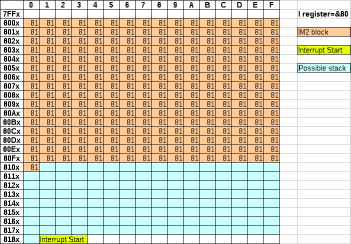
Interrupt Mode 2 uses the I register... Lets assume the I register
contains &80 ... the device that causes the interrupt will provide an
extra byte xx to make up an address &80xx ... What happens next is two
bytes are read in from the address &80xx and &80xx+1 ... and
this address is called!
For Example...
Suppose we're in IM2... and the device send byte &11... I contains
&80... the address called will be taken from &8011... at &8011
is byte &82... at &8012 is byte &81... so the address is
&8182
The effect is that the Z80 will call address &8182
We have no way to predict what the xx byte will contain... but we
know that the range the memory address will be chosen from.
What's the point of all this? well Interrupt Mode 1 requires us to alter
address &0038... but if that area is in use by something else, like
ROM or Screen Memory then we need an alternative that can work from
somewhere else, and the only option is Interrupt Mode 2
Interrupt Mode 2 - Practical use.
You need to decide on an address where your code which makes up
interrupt handler will actually reside, and both bytes of it's address
need to be the same... so it could be at &4040, or &5353... but it
can't be at 4422... The best choice is &8181
Next you need to allocate a block of 257 bytes... starting at a byte
origin... so &4000-&4100 (including &4100), or
&5000-&5100... the best choice is &8000!
now we write our chosen repeated address byte (&81) to every byte in
our block (&8000-&8100)... This is so that whatever address
is called, the same address will actually be executed (&8181)
We need to set I to the first byte in the address of our block
(&80)... then we enable Interrupt Mode 2
When the interrupt occurs Interrupt Mode 2 - whatever byte was added to
the I register, the interrupt will always end up calling &8181 -
and we can carry on the same as if we were just using Interrupt Mode 1
|
You may see
examples online that use a block of 257 &FF bytes in
the rom as the IM2 block, which would jump to &FFFF... this
works OK on the 48k, but does not work well on the 128k systems.
If you want to play it safe you can't do that... but using 257
bytes for the IM2 block may be tough on a 48k system! |
Why use
&8000 and &8181?
The ZX spectrum has issues with IM2 if the range is lower than
&8000, and (I think) higher than &C000... but the
&8000/&8181 option is rock solid, and the choice of
smarter minds than mine!... of course if you know what you're
doing you can put the IM2 block somewhere else... but the
&8000 range tends to be free on all systems, so this is as
good a choice as there is!
Is there a way to stop IM2 using so many
bytes?
No, there isn't... you'll have to use &8000-&8100 for the
filled block, and &8181 for the start of the interrupt handler
(you can just have a jump there to your real handler... one tip is
you can use the range &8001-&8180 for your stack, to use
up the 'spare space'... and reduce the pain of those lost bytes a
bit! |
 |
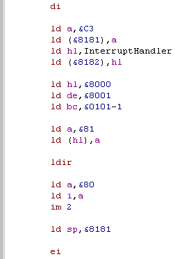
The Assembly code for using
the IM2 interrupt handler is pretty easy, it just takes a lot of
memory!
First we disable interrupts,
Then we put a jump to our interrupt code at &8181
Now we fill &8000-&8101 with the byte &81
We set I to &80, and the interrupt mode to IM2
for good measure, lets use the spare space for the stack pointer
we're done, so we just enable interrupts! |
 |
Remember that you
don' t NEED to use interrupts if you don't want to! They help
make timing easy (for updating music) and allow you to switch
colors midscreen, but if you don't need things like that, just
keep interrupts turned off!
You'll save some speed! and won't have to worry about all this
silliness
|
|
Lesson A3 - Simulating functionality for the
GBZ80
There may be times where we cannot use functions like the shadow
registers, IY or other functionality - either because we're using
the GBZ80 CPU (gameboy) or the firmware of a Z80 system need them
intact... but we need convert some code that already uses
them...
For this reason, it's worth looking at some 'simulated' commands
to do basic Z80 functions... they won't be as fast, but they will
work! |
|
|
|
|
|
If we want to
support the GBZ80 and Z80, we need to create two copies of these
macros - one which compiles to the true Z80 command and one that
compiles to the GBZ80 equivalent...
If we use only the macros in our code, we'll be able to support
both GB and other systems seamlessly!... if you want to see this
in action take a look at GrimeZ80!
|
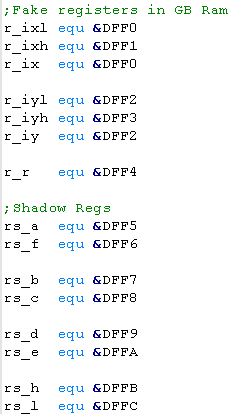
The first thing we will need to do
is allocate some memory for the registers we cannot use, the
examples shown are for the Gameboy,
We will use these to store the values the registers would hold. |
 |
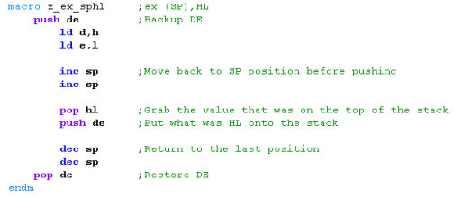
EX (SP),HL
This is a command which swaps the
top two bytes of the stack with the HL register... this command
does not exist on the Gameboy...
One way to fake this command is to push DE to the stack... then
move HL to DE... next popping off what was the top of the stack
into HL... then pushing back DE (which will have what HL had when
we started)
Finally we pop the original DE...
the result... DE is unchanged... HL and the top of the stack are
swapped!
|
 |
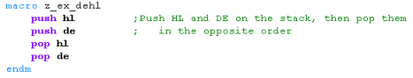
EX DE,HL
Swap the DE and HL register.
This one's easy, we just push HL and DE onto the stack... and pop
them off in the opposite order! |
 |
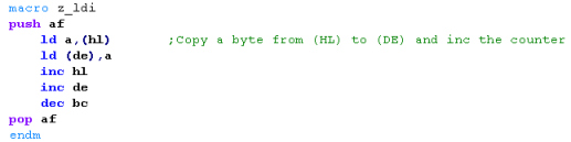
LDI
LDI is a popular command, but the
GBZ80 doesn't have it,
fortunately it's easy to fake... load from (HL) save it to (DE),
INC HL,DE and DEC BC
The real command doesn't affect A, so we push it to the stack
while we're working |
 |
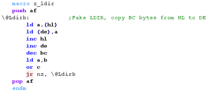
LDIR
LDIR is just the same, only we have to loop until BC is zero...
We use a 'local label' in our macro... Note: if you're not using
VASM you may need to change this, as other assemblers will
probably do it differently. |
 |
HALT
| Halt is a bit odd... the GBZ80 does have it, but there is a bug,
and it tends to skip the command after the HALT command in some
cases... therefore we will create a macro to do us the job! |
 |
 |
on a regular Z80... DI
HALT will lock up the CPU, but on the GBZ80 it will not, however
there is a bug in the command...
The next command following a HALT will be skipped, so we need to
put a NOP after the HALT command
On the GBZ80 HALT is used to save power, hence the difference in
it's functionality |
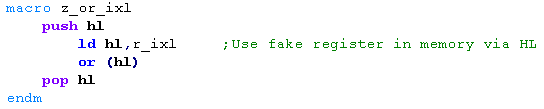
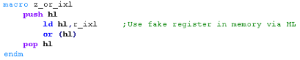
OR (IXL)...
IXH,IXL,IYH and IYL do not exist on the GBZ80... we have memory
areas we'll use to fake them...
We'll use the HL register to point to the 'fake register', and OR
(HL) to do the job... this means the flags and A will be
correct... we just need to back up HL in the stack while we do it.
We'll have to do the same for the other IX/IY 8 bit registers. |
|
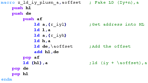
LD (IX+n),a
The GBZ80 has not indirect
registers, so it will be tough to fake, but we can do it!
We'll load the fake IX/IY into HL... add the offset in DE - and
then write A to the resulting address.
We'll need to do something similar for LD (IX+n),h and others.... |
 |
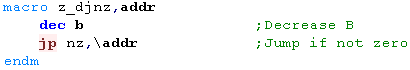
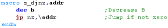
DJNZ label
DJNZ is pretty simple - but the GBZ80 doesn't have it...
All we need to do is DEC B... then JumP if it's not Zero |
 |
LD A,R
| I use the R register as a random
number source, here is a simple 'random' number generator, which
uses the last R value, and the state of various registers for a
randomization source. |
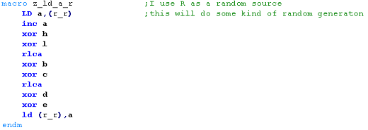 |
This command
will emulate the use of R as a random seed... if you were using
it for something else, you'll have to write your own command!
|
 |
LD A,IYL... LD IYL,A...
| Loading A to or from the fake registers is very easy... we just
Read or Write directly into the ram address we're using for the
fake register. |


|
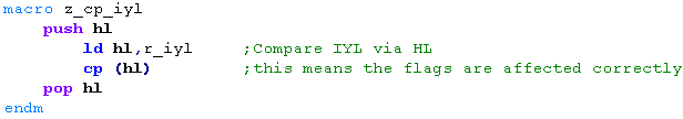
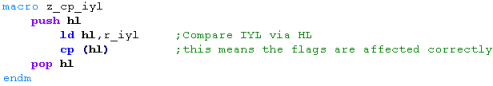
CP IYL...
| If we need to compare with one of
the 8 bit parts of IX or IY, we can do this by setting HL to the
address of the register, and using CP (HL)... this means A
and F will be set correctly. |
 |
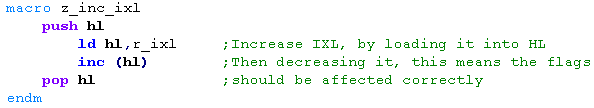
INC/DEC IXL...
| We do pretty much the same for INC
and DEC... |
 |
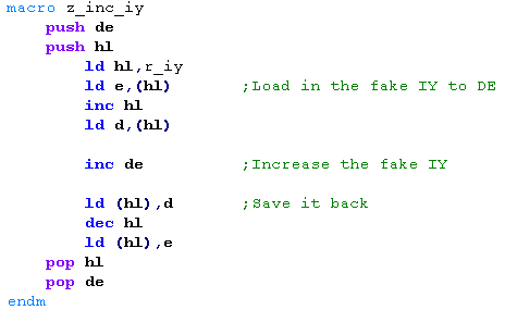
INC/DEC IX...
when we want to INC (or dec) IX or
IY one way we can do it is to read in the pair into DE via (HL)...
do the INC... then write it back.
This is a pain, but the GBZ80 can't read a DE/HL or any other pair
from an address either, so we have to do something! |
 |
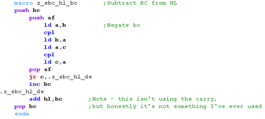
SBC HL,DE.... (Actually SUB HL,DE)
When we want to do subtraction, we
can do this by using CPL to flip the bits of the destination and
then use the ADD command...
note: we're ignoring the Carry... the reason for this is I've
never actually needed the Carry element of SBC - so I've not
emulated it here! |
 |
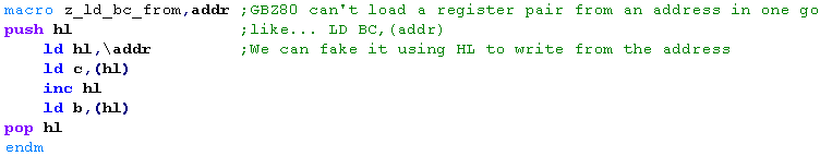
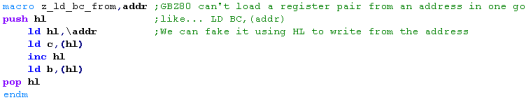
LD BC,(addr)...
If we want to load in a pair of registers from an address then
the GBZ80 can't do this in one go... but we can fake it by setting
HL to the address, and reading in the pair.
If we want to do the opposite... LD (addr),BC... we just do the
opposite! |
 |
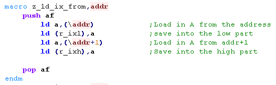
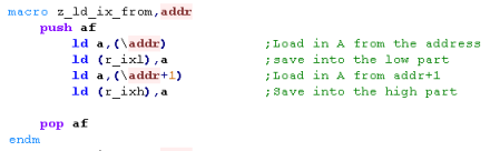
LD IX,(addr)...
| If we're reading into our fake
registers, we don't need to use HL at all, we can just do it with
the accumulator. |
 |
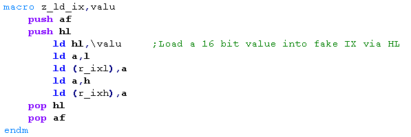
LD IX,$nnnn
If we want to load a 2-byte word
into IX or IY, we can do it by first loading the value into HL and
then moving the result into the destination...
Depending on our assembler we could do this with remainder
division using / % or other symbols if supported... but this is
probably the more compatible method. |
 |
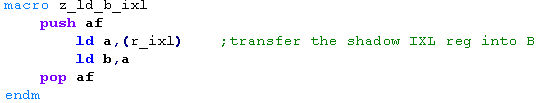
LD B,IXL
| When we want to transfer from a
register like IXL, we can do this via the A register, then
transfer it to the B reg. |
 |
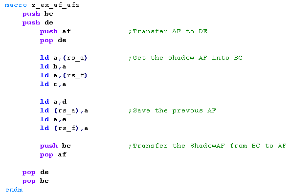
EX AF,AF'
Swapping AF with the shadow AF
takes quite a few commands, first we'll back AF up into DE, then
we'll read the current 'shadow AF' into BC... then we'll
store the copy of AF into the fake 'shadow AF'
We'll have to PUSH and POP BC and DE to protect them |
 |
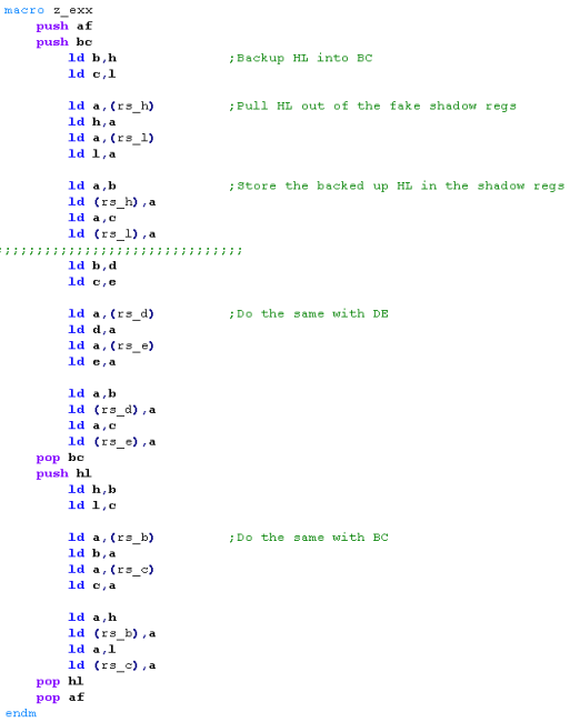
EXX
EXX swaps the main registers
BC,DE,HL with the shadow versions,
Using our fake 'memory registers' to do this will be a pain, but
we can do it!
We have to use a pair of registers to store one of the pairs
(first we'll use BC)... we'll back up a pair, read it in from the
memory registers...then we'll use the backup to update the shadow
registers....
First we do HL (using BC as backup)..... then we do DE.... finally
we do BC (using HL as a backup) |
 |
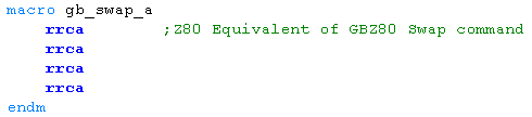
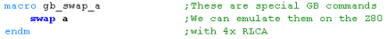
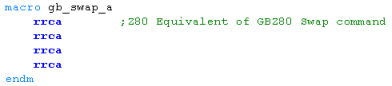
SWAP (GBZ80 only!!!)
| The swap command of the GBZ80 swaps
two nibbles in a byte - a nice command to have, but if we want to
write code that works on the Z80 and GBZ80 then we will have to
fake the GBZ80 command on the Z80! |
 |
Lesson A4 - Removing Self Modifying Code
If we're looking to move from a RAM based program, to one that can
run from cartridge memory, we may need to take a program that uses
self modifying code, and convert it so it can be executed from
ROM... as an example lets take a look at my conversion of
ArkosTracker to the Master System! |
|
|
|
|
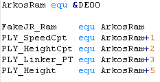
Creating a 'Modifyable store'
While we can make the program code read only, we still need
enough 'data space' for the bytes that were being modified...
All the labels that were being modified... and the number of bytes
that were being changed need to be allocated in the RAM of the
machine. |
 |
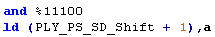
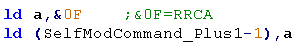
Self-Modified Load command
This is pretty much the simplest command... a is being loaded
with a value, and that value is being altered with self modified
code.
Note the +1 is removed... it now has no meaning, as it was being
used to point to the second byte of the line being modified
Of course 'PLY_Track1_InstrumentSpeed' is now just an 'allocated'
byte in the 'dataspace' mentioned above.... it is defined by an
EQU command
The same can be done with 16 bit commands like LD BC,xxxx |
Was:

 |
Now:

 |
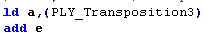
Self-Modified Add command
| In this example, the parameter in an ADD command was being
modified - we need to add an address... however there is no ADD
(addr) command... so I have swapped around the commands, and
loaded the value into A and added E... rather than loading E into
A and adding the value. |
Was:
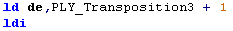
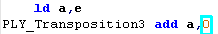 |
Now:
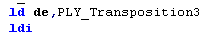
 |
Self-Modified CP command
Here we have an instance where the
Value being compared is being modified.
We can make this into ROM, by storing the value to compare to in
RAM... and pointing HL to that ram store... then using CP (HL) |
Was:

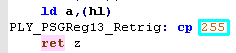 |
Now:

 |
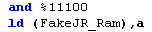
Self-Modified JR command
This one is rather tricky... A Jump
Relative command is being used to skip some commands, but the
number of commands being skipped will vary
I've decided to make a 'Fake JR' command which will simulate a
JR.. .but will take it's parameter from RAM, rather than the
command line...
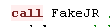
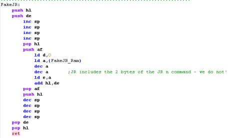
The FakeJR command is called.. and it reads in it's calling
address, then adds FakeJR_RAM to it... the result is a jump
affected in the same way as a JR xx ... where xx can be self
modified...
Note: The example code here will not work with a negative jump -
but arkos tracker does not do that. |
Was:

|
Now:
 |
|
This JR
substitute only works for POSITIVE JR commands... also if the JR
command only has one or two possible versions, it would probably
be easier to replace it with a set of CMP and JR Z commands! |
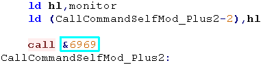
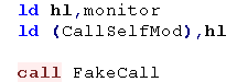
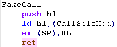
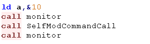
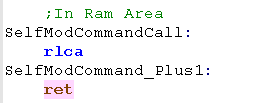
Self-Modified CALL or JP command
It wasn't needed in Arkostracker,
but there may be times we need to use a Self-modified CALL
We can emulate this by using the EX (SP),HL command to swap a
value from a memory address onto the top of the stack...
This will also work with a self-modified JumpP... Just use JP
FakeCall instead! |
Was:
|
Now:
 |
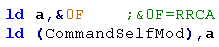
Self-Modified ASM commands
There may be times when self
modifying code to replace whole commands...
For example here we se a RLCA can be replaced with a RRCA by
self-modifying code...
One option would be to read in a temporary memory byte, and use a
ComPare command to switch between the possible commands which may
want to be executed.
An Alternate option is to allow this to run from ROM would be to
call to a command in ram, and self modify that command... this
would work fine for a RLCA type command, but would cause problems
for a PUSH or POP command that was modified |
Was:
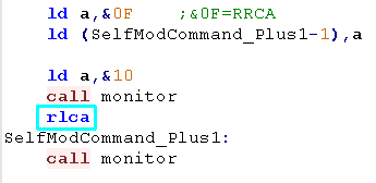 |
Now:
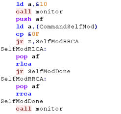
Alternate:
 |
These are just
examples of possible ways to remove self modifying code - There
will be better ways depending on the exact circumstances of the
program...
If you really get stuck, maybe you can run some or all of the
code from ram - if you have enough free!
|
|