
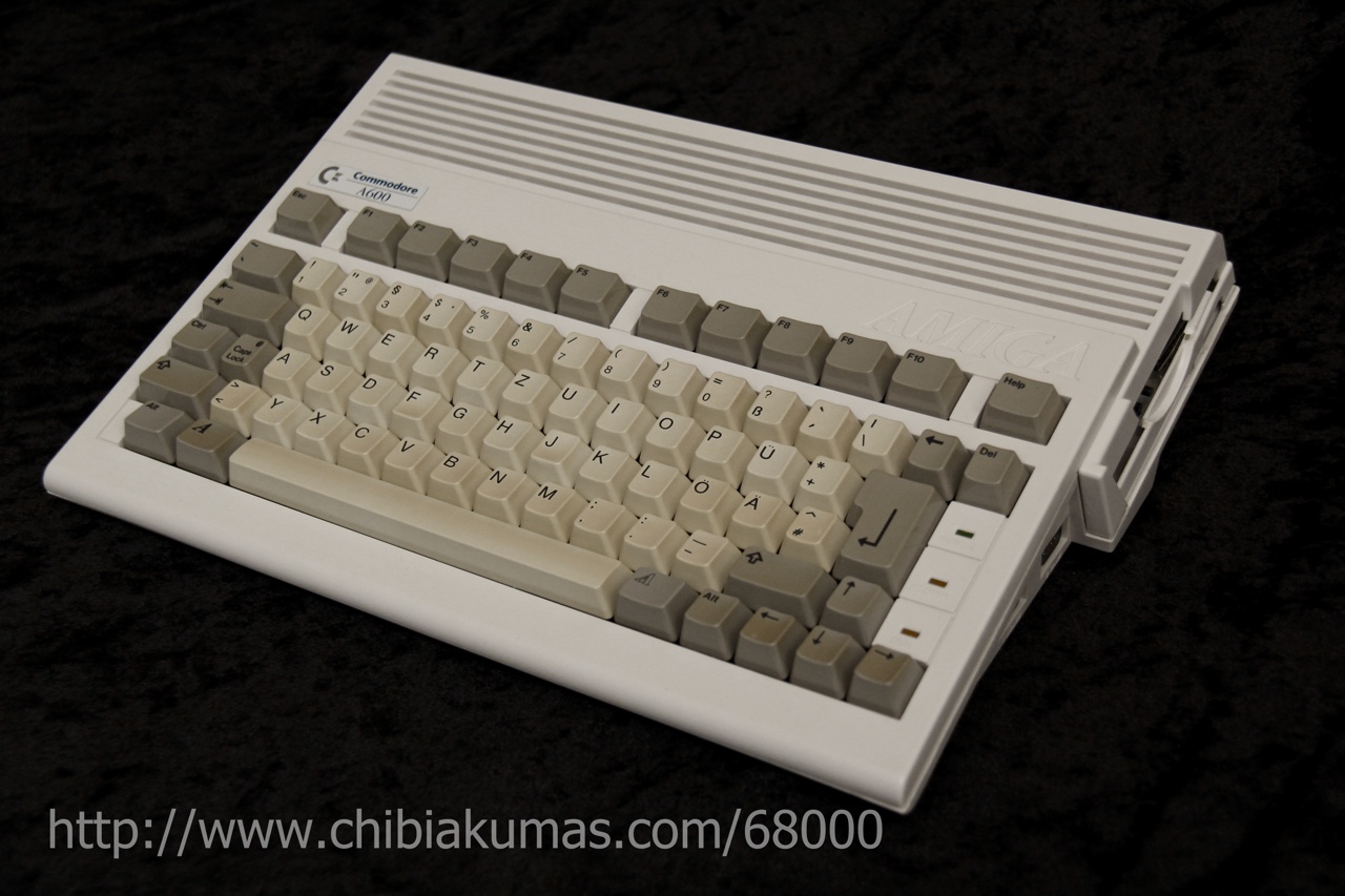
68000 Assembly programming for the The Commodore Amiga (500)
| The Amiga was the first hugely
popular 16 bit home computer, and was the envy of all the 8 bit
owners in the 80's and early 90's... With graphics closer to the arcade, and impressive digital sound, the Amiga dominated home computing until the 486's stared to give the PC superior power... while often graphically comparable to the Atari ST... the Amiga's superior sound... with 4 PCM channels brought high quality music to games and amateur musicians |
 |
 |
Specs:
|
 |
Useful Documents
Amiga
Hardware Ref Manual - The best hardware document I've found
ChibiAkumas Tutorials
Palette Definitions
| Palette definitions on the Amiga are performed by writing to
memory registers between $DFF180 and $DFF1BE Definitions can be performed by writing a word to these registers, with 4 bits per channel in the format shown to the right |
|
|||||||||||||||||||||||||||||||||||||||||||||||||||||||||||||||||||||||||||||||||||||||||||||||||||
| There are a set of 32 words between
$DFF180 and $DFF1BE, We don't actually set these directly, we want to change them within our copperlist! |
|
Memory Map
| From | To | Description |
| 000000 | 03FFFF | 256K Chip RAM (A1000 Chip RAM,1st 256K for A500/A2000) |
| 040000 | 07FFFF | 256K bytes of Chip RAM (2nd 256K for A500/A2000) |
| 080000 | 0FFFFF | 512K Extended chip RAM (to 1 MB for A2000). |
| 100000 | 1FFFFF | Reserved. Do not use. |
| 200000 | 9FFFFF | Primary 8 MB Auto-config space . |
| A00000 | BEFFFF | Reserved. Do not use. |
| BFD000 | BFDF00 | 8520-B (access at even-byte addresses only) |
| BFE001 | BFEF01 | 8520-A (access at odd-byte addresses only) |
| C00000 | DFEFFF | Reserved. Do not use. |
| C00000 | D7FFFF | Internal expansion (slow) memory (on some systems). |
| D80000 | DBFFFF | Reserved. Do not use. |
| DC0000 | DCFFFF | Real time clock (not accessable on all systems). |
| DFF000 | DFFFFF | Chip registers. |
| E00000 | E7FFFF | Reserved. Do not use. |
| E80000 | E8FFFF | Auto-config space |
| E90000 | EFFFFF | Secondary auto-config space (usually 64K I/O boards). |
| F00000 | FBFFFF | Reserved. Do not use. |
| FC0000 | FFFFFF | 256K System ROM. |
"Chip Registers" System Registers appear in the memory address rage $DFF000-$DFFFFFF... However they will appear without the $DFF prefix when used in command sequences for the "Copper" coprocesor
| NAME |
|
ADD | R/WD | Chip | Function |
| BLTDDAT | & | *000 | ER | A | Blitter destination early read (dummy address) |
| DMACONR | *002 | R | AP | DMA control (and blitter status) read | |
| VPOSR | *004 | R | A( E ) | Read vert most signif. bit (and frame flop) | |
| VHPOSR | *006 | R | A | Read vert and horiz. position of beam | |
| DSKDATR | & | *008 | ER | P | Disk data early read (dummy address) |
| JOY0DAT | *00A | R | D | Joystick-mouse 0 data (vert,horiz) | |
| JOY1DAT | *00C | R | D | Joystick-mouse 1 data (vert,horiz) | |
| CLXDAT | *00E | R | D | Collision data register (read and clear) | |
| ADKCONR | *010 | R | P | Audio, disk control register read | |
| POT0DAT | *012 | R | P( E ) | Pot counter pair 0 data (vert,horiz) | |
| POT1DAT | *014 | R | P( E ) | Pot counter pair 1 data (vert,horiz) | |
| POTGOR | *016 | R | P | Pot port data read (formerly POTINP) | |
| SERDATR | *018 | R | P | Serial port data and status read | |
| DSKBYTR | *01A | R | P | Disk data byte and status read | |
| INTENAR | *01C | R | P | Interrupt enable bits read | |
| INTREQR | *01E | R | P | Interrupt request bits read | |
| DSKPTH | + | *020 | W | A( E ) | Disk pointer (high 3 bits, 5 bits if ECS) |
| DSKPTL | + | *022 | W | A | Disk pointer (low 15 bits) |
| DSKLEN | *024 | W | P | Disk length | |
| DSKDAT | & | *026 | W | P | Disk DMA data write |
| REFPTR | & | *028 | W | A | Refresh pointer |
| VPOSW | *02A | W | A | Write vert most signif. bit (and frame flop) | |
| VHPOSW | *02C | W | A | Write vert and horiz position of beam | |
| COPCON | *02E | W | A( E ) | Coprocessor control register (CDANG) | |
| SERDAT | *030 | W | P | Serial port data and stop bits write | |
| SERPER | *032 | W | P | Serial port period and control | |
| POTGO | *034 | W | P | Pot port data write and start | |
| JOYTEST | *036 | W | D | Write to all four joystick-mouse counters at once | |
| STREQU | & | *038 | S | D | Strobe for horiz sync with VB and EQU |
| STRVBL | & | *03A | S | D | Strobe for horiz sync with VB (vert. blank) |
| STRHOR | & | *03C | S | DP | Strobe for horiz sync |
| STRLONG | & | *03E | S | D( E ) | Strobe for identification of long horiz. Line. |
| BLTCON0 | ~040 | W | A | Blitter control register 0 | |
| BLTCON1 | ~042 | W | A( E ) | Blitter control register 1 | |
| BLTAFWM | ~044 | W | A | Blitter first word mask for source A | |
| BLTALWM | ~046 | W | A | Blitter last word mask for source A | |
| BLTCPTH | + | ~048 | W | A | Blitter pointer to source C (high 3 bits) |
| BLTCPTL | + | ~04A | W | A | Blitter pointer to source C (low 15 bits) |
| BLTBPTH | + | ~04C | W | A | Blitter pointer to source B (high 3 bits) |
| BLTBPTL | + | ~04E | W | A | Blitter pointer to source B (low 15 bits) |
| BLTAPTH | + | ~050 | W | A( E ) | Blitter pointer to source A (high 3 bits) |
| BLTAPTL | + | ~052 | W | A | Blitter pointer to source A (low 15 bits) |
| BLTDPTH | + | ~054 | W | A | Blitter pointer to destination D (high 3 bits) |
| BLTDPTL | + | ~056 | W | A | Blitter pointer to destination D (low 15 bits) |
| BLTSIZE | ~058 | W | A | Blitter start and size (window width,height) | |
| BLTCON0L | ~05A | W | A( E ) | Blitter control 0, lower 8 bits (minterms) | |
| BLTSIZV | ~05C | W | A( E ) | Blitter V size (for 15 bit vertical size) | |
| BLTSIZH | ~05E | W | A( E ) | Blitter H size and start (for 11 bit H size) | |
| BLTCMOD | ~060 | W | A | Blitter modulo for source C | |
| BLTBMOD | ~062 | W | A | Blitter modulo for source B | |
| BLTAMOD | ~064 | W | A | Blitter modulo for source A | |
| BLTDMOD | ~066 | W | A | Blitter modulo for destination D | |
| ~068 | |||||
| ~06A | |||||
| ~06C | |||||
| ~06E | |||||
| BLTCDAT | % | ~070 | W | A | Blitter source C data register |
| BLTBDAT | % | ~072 | W | A | Blitter source B data register |
| BLTADAT | % | ~074 | W | A | Blitter source A data register |
| ~076 | |||||
| SPRHDAT | ~078 | W | A( E ) | Ext. logic UHRES sprite pointer and data id | |
| ~07A | |||||
| DENISEID | ~07C | R | D( E ) | Chip revision level for Denise (video out chip) | |
| DSKSYNC | ~07E | W | P | Disk sync pattern register for disk read | |
| COP1LCH | + | 80 | W | A( E ) | Coprocessor first location register (high 3 bits, high 5 bits if ECS) |
| COP1LCL | + | 82 | W | A | Coprocessor first location register (low 15 bits) |
| COP2LCH | + | 84 | W | A( E ) | Coprocessor second location register (high 3 bits, high 5 bits if ECS) |
| COP2LCL | + | 86 | W | A | Coprocessor second location register (low 15 bits) |
| COPJMP1 | 88 | S | A | Coprocessor restart at first location | |
| COPJMP2 | 08A | S | A | Coprocessor restart at second location | |
| COPINS | 08C | W | A | Coprocessor instruction fetch identify | |
| DIWSTRT | 08E | W | A | Display window start (upper left vert-horiz position) | |
| DIWSTOP | 90 | W | A | Display window stop (lower right vert.-horiz. Position) | |
| DDFSTRT | 92 | W | A | Display bitplane data fetch start (horiz. Position) | |
| DDFSTOP | 94 | W | A | Display bitplane data fetch stop (horiz. position) | |
| DMACON | 96 | W | ADP | DMA control write (clear or set) | |
| CLXCON | 98 | W | D | Collision control | |
| INTENA | 09A | W | P | Interrupt enable bits (clear or set bits) | |
| INTREQ | 09C | W | P | Interrupt request bits (clear or set bits) | |
| ADKCON | 09E | W | P | Audio, disk, UART control | |
| AUD0LCH | + | 0A0 | W | A( E ) | Audio channel 0 (L) location (high 3 bits, 5 if ECS) |
| AUD0LCL | + | 0A2 | W | A | Audio channel 0 (L) location (low 15 bits) |
| AUD0LEN | 0A4 | W | P | Audio
channel
0 (L) length (in words) |
|
| AUD0PER | 0A6 | W | P( E ) | Audio channel 0 (L) period | |
| AUD0VOL | 0A8 | W | P | Audio channel 0 (L) volume | |
| AUD0DAT | & | 0AA | W | P | Audio channel 0 (L) data |
| 0AC | |||||
| 0AE | |||||
| AUD1LCH | + | 0B0 | W | A | Audio channel 1 (R) location (high 3 bits) |
| AUD1LCL | + | 0B2 | W | A | Audio channel 1 (R) location (low 15 bits) |
| AUD1LEN | 0B4 | W | P | Audio channel 1 (R) length (in words) | |
| AUD1PER | 0B6 | W | P | Audio channel 1 (R) period | |
| AUD1VOL | 0B8 | W | P | Audio channel 1 (R) volume | |
| AUD1DAT | & | 0BA | W | P | Audio channel 1 (R) data |
| 0BC | |||||
| 0BE | |||||
| AUD2LCH | + | 0C0 | W | A | Audio channel 2 (L) location (high 3 bits) |
| AUD2LCL | + | 0C2 | W | A | Audio channel 2 (L) location (low 15 bits) |
| AUD2LEN | 0C4 | W | P | Audio channel 2 (L) length (in words) | |
| AUD2PER | 0C6 | W | P | Audio channel 2 (L) period | |
| AUD2VOL | 0C8 | W | P | Audio channel 2 (L) volume | |
| AUD2DAT | & | 0CA | W | P | Audio channel 2 (L) data |
| 0CC | |||||
| 0CE | |||||
| AUD3LCH | + | 0D0 | W | A | Audio channel 3 (R) location (high 3 bits) |
| AUD3LCL | + | 0D2 | W | A | Audio channel 3 (R) location (low 15 bits) |
| AUD3LEN | 0D4 | W | P | Audio channel 3 (R) length (in words) | |
| AUD3PER | 0D6 | W | P | Audio channel 3 (R) period | |
| AUD3VOL | 0D8 | W | P | Audio channel 3 (R) volume | |
| AUD3DAT | & | 0DA | W | P | Audio channel 3 (R) data |
| 0DC | |||||
| 0DE | |||||
| BPL1PTH | + | 0E0 | W | A | Bitplane 1 pointer (high 3 bits) |
| BPL1PTL | + | 0E2 | W | A | Bitplane 1 pointer (low 15 bits) |
| BPL2PTH | + | 0E4 | W | A | Bitplane 2 pointer (high 3 bits) |
| BPL2PTL | + | 0E6 | W | A | Bitplane 2 pointer (low 15 bits) |
| BPL3PTH | + | 0E8 | W | A | Bitplane 3 pointer (high 3 bits) |
| BPL3PTL | + | 0EA | W | A | Bitplane 3 pointer (low 15 bits) |
| BPL4PTH | + | 0EC | W | A | Bitplane 4 pointer (high 3 bits) |
| BPL4PTL | + | 0EE | W | A | Bitplane 4 pointer (low 15 bits) |
| BPL5PTH | + | 0F0 | W | A | Bitplane 5 pointer (high 3 bits) |
| BPL5PTL | + | 0F2 | W | A | Bitplane 5 pointer (low 15 bits) |
| BPL6PTH | + | 0F4 | W | A | Bitplane 6 pointer (high 3 bits) |
| BPL6PTL | + | 0F6 | W | A | Bitplane 6 pointer (low 15 bits) |
| 0F8 | |||||
| 0FA | |||||
| 0FC | |||||
| 0FE | |||||
| BPLCON0 | 100 | W | AD( E ) | Bitplane control register (misc. control bits) | |
| BPLCON1 | 102 | W | D | Bitplane control reg. (scroll value PF1, PF2) | |
| BPLCON2 | 104 | W | D( E ) | Bitplane control reg. (priority control) | |
| BPLCON3 | 106 | W | D( E ) | Bitplane control (enhanced features) | |
| BPL1MOD | 108 | W | A | Bitplane modulo (odd planes) | |
| BPL2MOD | 10A | W | A | Bitplane modulo (even planes) | |
| 10C | |||||
| 10E | |||||
| BPL1DAT | & | 110 | W | D | Bitplane 1 data (parallel-to-serial convert) |
| BPL2DAT | & | 112 | W | D | Bitplane 2 data (parallel-to-serial convert) |
| BPL3DAT | & | 114 | W | D | Bitplane 3 data (parallel-to-serial convert) |
| BPL4DAT | & | 116 | W | D | Bitplane 4 data (parallel-to-serial convert) |
| BPL5DAT | & | 118 | W | D | Bitplane 5 data (parallel-to-serial convert) |
| BPL6DAT | & | 11A | W | D | Bitplane 6 data (parallel-to-serial convert) |
| 11C | |||||
| 11E | |||||
| SPR0PTH | + | 120 | W | A | Sprite 0 pointer (high 3 bits) |
| SPR0PTL | + | 122 | W | A | Sprite 0 pointer (low 15 bits) |
| SPR1PTH | + | 124 | W | A | Sprite 1 pointer (high 3 bits) |
| SPR1PTL | + | 126 | W | A | Sprite 1 pointer (low 15 bits) |
| SPR2PTH | + | 128 | W | A | Sprite 2 pointer (high 3 bits) |
| SPR2PTL | + | 12A | W | A | Sprite 2 pointer (low 15 bits) |
| SPR3PTH | + | 12C | W | A | Sprite 3 pointer (high 3 bits) |
| SPR3PTL | + | 12E | W | A | Sprite 3 pointer (low 15 bits) |
| SPR4PTH | + | 130 | W | A | Sprite 4 pointer (high 3 bits) |
| SPR4PTL | + | 132 | W | A | Sprite 4 pointer (low 15 bits) |
| SPR5PTH | + | 134 | W | A | Sprite 5 pointer (high 3 bits) |
| SPR5PTL | + | 136 | W | A | Sprite 5 pointer (low 15 bits) |
| SPR6PTH | + | 138 | W | A | Sprite 6 pointer (high 3 bits) |
| SPR6PTL | + | 13A | W | A | Sprite 6 pointer (low 15 bits) |
| SPR7PTH | + | 13C | W | A | Sprite 7 pointer (high 3 bits) |
| SPR7PTL | + | 13E | W | A | Sprite 7 pointer (low 15 bits) |
| SPR0POS | % | 140 | W | AD | Sprite 0 vert-horiz start position data |
| SPR0CTL | % | 142 | W | AD( E ) | Sprite 0 vert stop position and control data |
| SPR0DATA | % | 144 | W | D | Sprite 0 image data register A |
| SPR0DATB | % | 146 | W | D | Sprite 0 image data register B |
| SPR1POS | % | 148 | W | AD | Sprite 1 vert-horiz start position |
| SPR1CTL | % | 14A | W | AD | Sprite 1 vert stop position and |
| SPR1DATA | % | 14C | W | D | Sprite 1 image data register A |
| SPR1DATB | % | 14E | W | D | Sprite 1 image data register B |
| SPR2POS | % | 150 | W | AD | Sprite 2 vert-horiz start position data |
| SPR2CTL | % | 152 | W | AD | Sprite 2 vert stop position and control data |
| SPR2DATA | % | 154 | W | D | Sprite 2 image data register A |
| SPR2DATB | % | 156 | W | D | Sprite 2 image data register B |
| SPR3POS | % | 158 | W | AD | Sprite 3 vert-horiz start position data |
| SPR3CTL | % | 15A | W | AD | Sprite 3 vert stop position and control data |
| SPR3DATA | % | 15C | W | D | Sprite 3 image data register A |
| SPR3DATB | % | 15E | W | D | Sprite 3 image data register B |
| SPR4POS | % | 160 | W | AD | Sprite 4 vert-horiz start position data |
| SPR4CTL | % | 162 | W | AD | Sprite 4 vert stop position and control data |
| SPR4DATA | % | 164 | W | D | Sprite 4 image data register A |
| SPR4DATB | % | 166 | W | D | Sprite 4 image data register B |
| SPR5POS | % | 168 | W | AD | Sprite 5 vert-horiz start position data |
| SPR5CTL | % | 16A | W | AD | Sprite 5 vert stop position and control data |
| SPR5DATA | % | 16C | W | D | Sprite 5 image data register A |
| SPR5DATB | % | 16E | W | D | Sprite 5 image data register B |
| SPR6POS | % | 170 | W | AD | Sprite 6 vert-horiz start position data |
| SPR6CTL | % | 172 | W | AD | Sprite 6 vert stop position and control data |
| SPR6DATA | % | 174 | W | D | Sprite 6 image data register A |
| SPR6DATB | % | 176 | W | D | Sprite 6 image data register B |
| SPR7POS | % | 178 | W | AD | Sprite 7 vert-horiz start position data |
| SPR7CTL | % | 17A | W | AD | Sprite 7 vert stop position and control data |
| SPR7DATA | % | 17C | W | D | Sprite 7 image data register A |
| SPR7DATB | % | 17E | W | D | Sprite 7 image data register B |
| COLOR00 | 180 | W | D | Color table 00 | |
| COLOR01 | 182 | W | D | Color table 01 | |
| COLOR02 | 184 | W | D | Color table 02 | |
| COLOR03 | 186 | W | D | Color table 03 | |
| COLOR04 | 188 | W | D | Color table 04 | |
| COLOR05 | 18A | W | D | Color table 05 | |
| COLOR06 | 18C | W | D | Color table 06 | |
| COLOR07 | 18E | W | D | Color table 07 | |
| COLOR08 | 190 | W | D | Color table 08 | |
| COLOR09 | 192 | W | D | Color table 09 | |
| COLOR10 | 194 | W | D | Color table 10 | |
| COLOR11 | 196 | W | D | Color table 11 | |
| COLOR12 | 198 | W | D | Color table 12 | |
| COLOR13 | 19A | W | D | Color table 13 | |
| COLOR14 | 19C | W | D | Color table 14 | |
| COLOR15 | 19E | W | D | Color table 15 | |
| COLOR16 | 1A0 | W | D | Color table 16 | |
| COLOR17 | 1A2 | W | D | Color table 17 | |
| COLOR18 | 1A4 | W | D | Color table 18 | |
| COLOR19 | 1A6 | W | D | Color table 19 | |
| COLOR20 | 1A8 | W | D | Color table 20 | |
| COLOR21 | 1AA | W | D | Color table 21 | |
| COLOR22 | 1AC | W | D | Color table 22 | |
| COLOR23 | 1AE | W | D | Color table 23 | |
| COLOR24 | 1B0 | W | D | Color table 24 | |
| COLOR25 | 1B2 | W | D | Color table 25 | |
| COLOR26 | 1B4 | W | D | Color table 26 | |
| COLOR27 | 1B6 | W | D | Color table 27 | |
| COLOR28 | 1B8 | W | D | Color table 28 | |
| COLOR29 | 1BA | W | D | Color table 29 | |
| COLOR30 | 1BC | W | D | Color table 30 | |
| COLOR31 | 1BE | W | D | Color table 31 | |
| HTOTAL | 1C0 | W | A( E ) | Highest number count, horiz line (VARBEAMEN=1) | |
| HSSTOP | 1C2 | W | A( E ) | Horizontal line position for HSYNC stop | |
| HBSTRT | 1C4 | W | A( E ) | Horizontal line position for HBLANK start | |
| HBSTOP | 1C6 | W | A( E ) | Horizontal line position for HBLANK stop | |
| VTOTAL | 1C8 | W | A( E ) | Highest numbered vertical line (VARBEAMEN=1) | |
| VSSTOP | 1CA | W | A( E ) | Vertical line position for VSYNC stop | |
| VBSTRT | 1CC | W | A( E ) | Vertical line for VBLANK start | |
| VBSTOP | 1CE | W | A( E ) | Vertical line for VBLANK stop | |
| 1D0 | Reserved | ||||
| 1D2 | Reserved | ||||
| 1D4 | Reserved | ||||
| 1D6 | Reserved | ||||
| 1D8 | Reserved | ||||
| 1DA | Reserved | ||||
| BEAMCON0 | 1DC | W | A( E ) | Beam counter control register (SHRES,PAL) | |
| HSSTRT | 1DE | W | A( E ) | Horizontal sync start (VARHSY) | |
| VSSTRT | 1E0 | W | A( E ) | Vertical sync start (VARVSY) | |
| HCENTER | 1E2 | W | A( E ) | Horizontal position for Vsync on interlace | |
| DIWHIGH | 1E4 | W | AD( E ) | Display window -upper bits for start, |
Copper list commands
copperlist commands can set a chip register, or wait for a particluar screen position
| Word 1 | Word 2 | ||||||||||||||||||||||||||||||||||||
| F | E | D | C | B | A | 9 | 8 | |
7 | 6 | 5 | 4 | 3 | 2 | 1 | 0 |
|
F | E | D | C | B | A | 9 | 8 | |
7 | 6 | 5 | 4 | 3 | 2 | 1 | 0 | Command | Details | |
| 0 | 0 | 0 | 0 | 0 | 0 | 0 | n | n | n | n | n | n | n | n | 0 | D | D | D | D | D | D | D | D | D | D | D | D | D | D | D | D | Change setting | n= address to Change ($DFFnnn) D=new data for address | ||||
| V | V | V | V | V | V | V | V | H | H | H | H | H | H | H | 1 | v | v | v | v | v | v | v | v | h | h | h | h | h | h | h | 1 | wait for pos | V=Vops H=Hpos v=Vpos Compare enable h=hpos compare enable | ||||
The copperlist should end with an infinite wait '#$fffffffe'
Hardware Sprites
| There are 8 hardware sprites on the Amiga, Hardware Sprites are 16
pixels wide, and can be any height... each sprite is 4 colors
(2bpp), but Sprites 0&1, 2&3 etc Hardware sprites use a set of pointers, pointing to a sprite table in 'Chip Ram'... this table defines a series of XY positions and bitmap data, that are used by the sprite DMA to define the image... The format of the header is as follows:
The end of each Sprite list ends 0,0 We need to define the pointers to the sprite data, we do this in the Copperlist in the following way: move.l #StartSprite0,d0 move.w #$0122,(a6)+ ; StartSprite0 pointer (low 15 bits) move.w d0,(a6)+ swap d0 move.w #$0120,(a6)+ ; StartSprite0 pointer (high 3 bits) move.w d0,(a6)+ The pointer addresses for other sprites are shown in the table below, you should define all the sprites, even if they point to an empty list... Once we've defined our sprites, we need to turn the sprite DMA on: move.w #%1000001000100000,DMACON ; DMA set ON - DMA control (and blitter status) read |
Sample Sprite Data: StartSprite0: dc.w $804A,$8800 ;Header dc.w $0001,$0304 ;Bitmap Data dc.w $0001,$0304 dc.w $0001,$0304 dc.w $0001,$0304 dc.w $0001,$0304 dc.w $0001,$0304 dc.w $0001,$0304 dc.w $0001,$0304 dc.w $A070,$A800 ;Header dc.w $0304,$0001,$0304 ;Bitmap Data dc.w $0001,$0304 dc.w $0001,$0304 dc.w $0001,$0304 dc.w $0001,$0304 dc.w $0001,$0304 dc.w $0001,$0304 dc.w $0001 dc.w 0,0 ;End of Sprites StartSprite1: dc.w $804A,$8880 ;header dc.w $0001,$0304 ;Bitmap Data dc.w $0001,$0304 dc.w $0010,$0403 dc.w $0010,$0403 dc.w $0304,$0001,$0304 dc.w $0010,$0403 dc.w $0010,$0403 dc.w $0001 dc.w 0,0 ;End of Sprites StartSprite2: ;Unused Sprites StartSprite3: StartSprite4: StartSprite5: StartSprite6: StartSprite7: dc.w 0,0 ;End of Sprites |
Sprite Pointers
The hardware sprites are defined by the following Chip Registers
| NAME |
|
ADD | R/WD | Chip | Function |
| DMACON | 96 | W | ADP | DMA control write (clear or set) | |
| SPR0PTH | + | 120 | W | A | Sprite 0 pointer (high 3 bits) |
| SPR0PTL | + | 122 | W | A | Sprite 0 pointer (low 15 bits) |
| SPR1PTH | + | 124 | W | A | Sprite 1 pointer (high 3 bits) |
| SPR1PTL | + | 126 | W | A | Sprite 1 pointer (low 15 bits) |
| SPR2PTH | + | 128 | W | A | Sprite 2 pointer (high 3 bits) |
| SPR2PTL | + | 12A | W | A | Sprite 2 pointer (low 15 bits) |
| SPR3PTH | + | 12C | W | A | Sprite 3 pointer (high 3 bits) |
| SPR3PTL | + | 12E | W | A | Sprite 3 pointer (low 15 bits) |
| SPR4PTH | + | 130 | W | A | Sprite 4 pointer (high 3 bits) |
| SPR4PTL | + | 132 | W | A | Sprite 4 pointer (low 15 bits) |
| SPR5PTH | + | 134 | W | A | Sprite 5 pointer (high 3 bits) |
| SPR5PTL | + | 136 | W | A | Sprite 5 pointer (low 15 bits) |
| SPR6PTH | + | 138 | W | A | Sprite 6 pointer (high 3 bits) |
| SPR6PTL | + | 13A | W | A | Sprite 6 pointer (low 15 bits) |
| SPR7PTH | + | 13C | W | A | Sprite 7 pointer (high 3 bits) |
| SPR7PTL | + | 13E | W | A | Sprite 7 pointer (low 15 bits) |
Hardware Sprites Pixel data
| The Sprites are always 16 pixels
wide, and by default 2bpp (4 colors)... each line of the sprite is
made up of 2 words of data... The first Word is effectively the 1st bitplane of the sprite. The second Word is effectively the 2st bitplane of the sprite. The third word will be the 1st bitplane of the 2nd line - and so on! If we attach Sprite 1 to Sprite 0 - we effectively increase it to 16 colors (4bpp) - adding an extra 2 bit-planes to the sprite! Note: We can only attach pairs of sprites, 0+1, 2+3, 4+5 or 6+7... we cannot attach sprite 0 to sprite 2! |
|
|||||||||||||||||||||||||||||||||||||||||||||||||||||||
4 color 2bpp Hardware Sprites Colors
4 color Hardware sprites use 3 colors from palette 17-31... color 0 is
always transparent... the colors vary depending on the sprite number
16 color sprites use colors 17-31
| Sprite number |
Palette numbers |
| 0, 1 |
17, 18, 19 |
| 2, 3 |
21, 22, 23 |
| 4, 5 |
25, 26, 27 |
| 6, 7 |
28, 29, 30 |
Sound ports on the Amiga
|
We need to use the Chip registers to control the sound, but unlike with the graphics, we're not going to use the Copper Chip. When we specify the address of the sample, we need this to be in Chip ram (Defined with 'Section ChipRAM,Data_c') |
 |
| Name | Address $DFFnnn |
Function | Bits | Details |
| DMACON | 096 | DMA control write (clear or set) | S-----E- ---DCBA | S=Set/Clr E=enable ABCD=Channnels |
| AUD0LCH | 0A0 | Audio channel 0 (L) location (high 3 bits, 5 if ECS) | -------- ---hhHHH | Address H � Must be within CHIP ram! |
| AUD0LCL | 0A2 | Audio channel 0 (L) location (low 15 bits) | LLLLLLLL LLLLLLL- | Address L � Must be within CHIP ram! |
| AUD0LEN | 0A4 | Audio channel 0 (L) length | DDDDDDDD DDDDDDDD | Data
Length (in words) |
| AUD0PER | 0A6 | Audio channel 0 (L) period | PPPPPPPP PPPPPPPP | Period
(High number=Low Pitch) |
| AUD0VOL | 0A8 | Audio channel 0 (L) volume | -------- --VVVVVV | V=Volume (64=max) |
| AUD0DAT | 0AA | Audio channel 0 (L) data | DDDDDDDD DDDDDDDD | Data |
| AUD1LCH | 0B0 | Audio channel 1 (R) location (high 3 bits) | -------- ---hhHHH | Address H � Must be within CHIP ram! |
| AUD1LCL | 0B2 | Audio channel 1 (R) location (low 15 bits) | LLLLLLLL LLLLLLL- | Address L � Must be within CHIP ram! |
| AUD1LEN | 0B4 | Audio channel 1 (R) length | DDDDDDDD DDDDDDDD | Data Length (in words) |
| AUD1PER | 0B6 | Audio channel 1 (R) period | PPPPPPPP PPPPPPPP | Period (High number=Low Pitch) |
| AUD1VOL | 0B8 | Audio channel 1 (R) volume | -------- --VVVVVV | V=Volume (64=max) |
| AUD1DAT | 0BA | Audio channel 1 (R) data | DDDDDDDD DDDDDDDD | Data |
| AUD2LCH | 0C0 | Audio channel 2 (L) location (high 3 bits) | -------- ---hhHHH | Address H � Must be within CHIP ram! |
| AUD2LCL | 0C2 | Audio channel 2 (L) location (low 15 bits) | LLLLLLLL LLLLLLL- | Address L � Must be within CHIP ram! |
| AUD2LEN | 0C4 | Audio channel 2 (L) length | DDDDDDDD DDDDDDDD | Data Length (in words) |
| AUD2PER | 0C6 | Audio channel 2 (L) period | PPPPPPPP PPPPPPPP | Period (High number=Low Pitch) |
| AUD2VOL | 0C8 | Audio channel 2 (L) volume | -------- --VVVVVV | V=Volume (64=max) |
| AUD2DAT | 0CA | Audio channel 2 (L) data | DDDDDDDD DDDDDDDD | Data |
| AUD3LCH | 0D0 | Audio channel 3 (R) location (high 3 bits) | -------- ---hhHHH | Address H � Must be within CHIP ram! |
| AUD3LCL | 0D2 | Audio channel 3 (R) location (low 15 bits) | LLLLLLLL LLLLLLL- | Address L � Must be within CHIP ram! |
| AUD3LEN | 0D4 | Audio channel 3 (R) length | DDDDDDDD DDDDDDDD | Data Length (in words) |
| AUD3PER | 0D6 | Audio channel 3 (R) period | PPPPPPPP PPPPPPPP | Period (High number=Low Pitch) |
| AUD3VOL | 0D8 | Audio channel 3 (R) volume | -------- --VVVVVV | V=Volume (64=max) |
| AUD3DAT | 0DA | Audio channel 3 (R) data | DDDDDDDD DDDDDDDD | Data |
 |
We're going to
use Channel 0 and Channel 1 to make a 'mono sound... As each channel is 16 bytes apart, we can specify the registers of Channel1 as Channel0's +16 - Eg: DFF0A2+16 for DFF0B2 This will make it easier to see we're changing the equivalent setting of Channel 1 when we set both together. |
Joystick reading
Joysticks on the Amiga connect to the Mouse ports... the data is
'encoded' in the bits of the Horizontal Data
| NAME | ADDR | FUNCTION |
| JOY0DAT | $DFF00A | Joystick-mouse 0 data (vert,horiz) |
| JOY1DAT | $DFF00C | Joystick-mouse 1 data (vert,horiz) |
To covert data from these ports into a traditional digital joystick direction, we need to do some logical operations.
| Direction | Represented
by Bits in $DFF0A/C |
| Right | 1 |
| Left | 9 |
| Down | 1 XOR 0 |
| UP | 9 XOR 8 |
We also need to get the joystick fire buttons from a different port:
| Address | Purpose |
| $BFE001 | FIR1 / FIR0 / RDY / TK0 / WPRO / CHNG / LED / OVL |
| $BFE201 | Direction for bits of port A ($BFE001)... 1=Out / 0=In |
Libraries
| Category | Offset Dec | |
Offset Hex | Meaning |
| exec | 30 | $ffe2 | -$001e | Supervisor(userFunction)(a5) |
| exec | 36 | $ffdc | -$0024 | ExitIntr()() |
| exec | 42 | $ffd6 | -$002a | Schedule()() |
| exec | 48 | $ffd0 | -$0030 | Reschedule()() |
| exec | 54 | $ffca | -$0036 | Switch()() |
| exec | 60 | $ffc4 | -$003c | Dispatch()() |
| exec | 66 | $ffbe | -$0042 | Exception()() |
| exec | 72 | $ffb8 | -$0048 | InitCode(startClass,version)(d0/d1) |
| exec | 78 | $ffb2 | -$004e | InitStruct(initTable,memory,size)(a1/a2,d0) |
| exec | 84 | $ffac | -$0054 | MakeLibrary(funcInit,structInit,libInit,dataSize,segList) |
| exec | 90 | $ffa6 | -$005a | MakeFunctions(target,functionArray,funcDispBase)(a0/a1/a2) |
| exec | 96 | $ffa0 | -$0060 | FindResident(name)(a1) |
| exec | 102 | $ff9a | -$0066 | InitResident(resident,segList)(a1,d1) |
| exec | 108 | $ff94 | -$006c | Alert(alertNum)(d7) |
| exec | 114 | $ff8e | -$0072 | Debug(flags)(d0) |
| exec | 120 | $ff88 | -$0078 | Disable()() |
| exec | 126 | $ff82 | -$007e | Enable()() |
| exec | 132 | $ff7c | -$0084 | Forbid()() |
| exec | 138 | $ff76 | -$008a | Permit()() |
| exec | 144 | $ff70 | -$0090 | SetSR(newSR,mask)(d0/d1) |
| exec | 150 | $ff6a | -$0096 | SuperState()() |
| exec | 156 | $ff64 | -$009c | UserState(sysStack)(d0) |
| exec | 162 | $ff5e | -$00a2 | SetIntVector(intNumber,interrupt)(d0/a1) |
| exec | 168 | $ff58 | -$00a8 | AddIntServer(intNumber,interrupt)(d0/a1) |
| exec | 174 | $ff52 | -$00ae | RemIntServer(intNumber,interrupt)(d0/a1) |
| exec | 180 | $ff4c | -$00b4 | Cause(interrupt)(a1) |
| exec | 186 | $ff46 | -$00ba | Allocate(freeList,byteSize)(a0,d0) |
| exec | 192 | $ff40 | -$00c0 | Deallocate(freeList,memoryBlock,byteSize)(a0/a1,d0) |
| exec | 198 | $ff3a | -$00c6 | AllocMem(byteSize,requirements)(d0/d1) |
| exec | 204 | $ff34 | -$00cc | AllocAbs(byteSize,location)(d0/a1) |
| exec | 210 | $ff2e | -$00d2 | FreeMem(memoryBlock,byteSize)(a1,d0) |
| exec | 216 | $ff28 | -$00d8 | AvailMem(requirements)(d1) |
| exec | 222 | $ff22 | -$00de | AllocEntry(entry)(a0) |
| exec | 228 | $ff1c | -$00e4 | FreeEntry(entry)(a0) |
| exec | 234 | $ff16 | -$00ea | Insert(list,node,pred)(a0/a1/a2) |
| exec | 240 | $ff10 | -$00f0 | AddHead(list,node)(a0/a1) |
| exec | 246 | $ff0a | -$00f6 | AddTail(list,node)(a0/a1) |
| exec | 252 | $ff04 | -$00fc | Remove(node)(a1) |
| exec | 258 | $fefe | -$0102 | RemHead(list)(a0) |
| exec | 264 | $fef8 | -$0108 | RemTail(list)(a0) |
| exec | 270 | $fef2 | -$010e | Enqueue(list,node)(a0/a1) |
| exec | 276 | $feec | -$0114 | FindName(list,name)(a0/a1) |
| exec | 282 | $fee6 | -$011a | AddTask(task,initPC,finalPC)(a1/a2/a3) |
| exec | 288 | $fee0 | -$0120 | RemTask(task)(a1) |
| exec | 294 | $feda | -$0126 | FindTask(name)(a1) |
| exec | 300 | $fed4 | -$012c | SetTaskPri(task,priority)(a1,d0) |
| exec | 306 | $fece | -$0132 | SetSignal(newSignals,signalSet)(d0/d1) |
| exec | 312 | $fec8 | -$0138 | SetExcept(newSignals,signalSet)(d0/d1) |
| exec | 318 | $fec2 | -$013e | Wait(signalSet)(d0) |
| exec | 324 | $febc | -$0144 | Signal(task,signalSet)(a1,d0) |
| exec | 330 | $feb6 | -$014a | AllocSignal(signalNum)(d0) |
| exec | 336 | $feb0 | -$0150 | FreeSignal(signalNum)(d0) |
| exec | 342 | $feaa | -$0156 | AllocTrap(trapNum)(d0) |
| exec | 348 | $fea4 | -$015c | FreeTrap(trapNum)(d0) |
| exec | 354 | $fe9e | -$0162 | AddPort(port)(a1) |
| exec | 360 | $fe98 | -$0168 | RemPort(port)(a1) |
| exec | 366 | $fe92 | -$016e | PutMsg(port,message)(a0/a1) |
| exec | 372 | $fe8c | -$0174 | GetMsg(port)(a0) |
| exec | 378 | $fe86 | -$017a | ReplyMsg(message)(a1) |
| exec | 384 | $fe80 | -$0180 | WaitPort(port)(a0) |
| exec | 390 | $fe7a | -$0186 | FindPort(name)(a1) |
| exec | 396 | $fe74 | -$018c | AddLibrary(library)(a1) |
| exec | 402 | $fe6e | -$0192 | RemLibrary(library)(a1) |
| exec | 408 | $fe68 | -$0198 | OldOpenLibrary(libName)(a1) |
| exec | 414 | $fe62 | -$019e | CloseLibrary(library)(a1) |
| exec | 420 | $fe5c | -$01a4 | SetFunction(library,funcOffset,newFunction)(a1,a0,d0) |
| exec | 426 | $fe56 | -$01aa | SumLibrary(library)(a1) |
| exec | 432 | $fe50 | -$01b0 | AddDevice(device)(a1) |
| exec | 438 | $fe4a | -$01b6 | RemDevice(device)(a1) |
| exec | 444 | $fe44 | -$01bc | OpenDevice(devName,unit,ioRequest,flags)(a0,d0/a1,d1) |
| exec | 450 | $fe3e | -$01c2 | CloseDevice(ioRequest)(a1) |
| exec | 456 | $fe38 | -$01c8 | DoIO(ioRequest)(a1) |
| exec | 462 | $fe32 | -$01ce | SendIO(ioRequest)(a1) |
| exec | 468 | $fe2c | -$01d4 | CheckIO(ioRequest)(a1) |
| exec | 474 | $fe26 | -$01da | WaitIO(ioRequest)(a1) |
| exec | 480 | $fe20 | -$01e0 | AbortIO(ioRequest)(a1) |
| exec | 486 | $fe1a | -$01e6 | AddResource(resource)(a1) |
| exec | 492 | $fe14 | -$01ec | RemResource(resource)(a1) |
| exec | 498 | $fe0e | -$01f2 | OpenResource(resName)(a1) |
| exec | 504 | $fe08 | -$01f8 | RawIOInit()() |
| exec | 510 | $fe02 | -$01fe | RawMayGetChar()() |
| exec | 516 | $fdfc | -$0204 | RawPutChar()() |
| exec | 522 | $fdf6 | -$020a | RawDoFmt(formatString,dataStream,putChProc,putChData) |
| exec | 528 | $fdf0 | -$0210 | GetCC()() |
| exec | 534 | $fdea | -$0216 | TypeOfMem(address)(a1) |
| exec | 540 | $fde4 | -$021c | Procure(semaport,bidMsg)(a0/a1) |
| exec | 546 | $fdde | -$0222 | Vacate(semaport)(a0) |
| exec | 552 | $fdd8 | -$0228 | OpenLibrary(libName,version)(a1,d0) |
| exec | 558 | $fdd2 | -$022e | InitSemaphore(sigSem)(a0) |
| exec | 564 | $fdcc | -$0234 | ObtainSemaphore(sigSem)(a0) |
| exec | 570 | $fdc6 | -$023a | ReleaseSemaphore(sigSem)(a0) |
| exec | 576 | $fdc0 | -$0240 | AttemptSemaphore(sigSem)(a0) |
| exec | 582 | $fdba | -$0246 | ObtainSemaphoreList(sigSem)(a0) |
| exec | 588 | $fdb4 | -$024c | ReleaseSemaphoreList(sigSem)(a0) |
| exec | 594 | $fdae | -$0252 | FindSemaphore(sigSem)(a1) |
| exec | 600 | $fda8 | -$0258 | AddSemaphore(sigSem)(a1) |
| exec | 606 | $fda2 | -$025e | RemSemaphore(sigSem)(a1) |
| exec | 612 | $fd9c | -$0264 | SumKickData()() |
| exec | 618 | $fd96 | -$026a | AddMemList(size,attributes,pri,base,name)(d0/d1/d2/a0/a1) |
| exec | 624 | $fd90 | -$0270 | CopyMem(source,dest,size)(a0/a1,d0) |
| exec | 630 | $fd8a | -$0276 | CopyMemQuick(source,dest,size)(a0/a1,d0) |
| exec | 636 | $fd84 | -$027c | CacheClearU()() |
| exec | 642 | $fd7e | -$0282 | CacheClearE(address,length,caches)(a0,d0/d1) |
| exec | 648 | $fd78 | -$0288 | CacheControl(cacheBits,cacheMask)(d0/d1) |
| exec | 654 | $fd72 | -$028e | CreateIORequest(port,size)(a0,d0) |
| exec | 660 | $fd6c | -$0294 | DeleteIORequest(iorequest)(a0) |
| exec | 666 | $fd66 | -$029a | CreateMsgPort()() |
| exec | 672 | $fd60 | -$02a0 | DeleteMsgPort(port)(a0) |
| exec | 678 | $fd5a | -$02a6 | ObtainSemaphoreShared(sigSem)(a0) |
| exec | 684 | $fd54 | -$02ac | AllocVec(byteSize,requirements)(d0/d1) |
| exec | 690 | $fd4e | -$02b2 | FreeVec(memoryBlock)(a1) |
| exec | 696 | $fd48 | -$02b8 | CreatePrivatePool(requirements,puddleSize,puddleThresh) |
| exec | 702 | $fd42 | -$02be | DeletePrivatePool(poolHeader)(a0) |
| exec | 708 | $fd3c | -$02c4 | AllocPooled(memSize,poolHeader)(d0/a0) |
| exec | 714 | $fd36 | -$02ca | FreePooled(memory,poolHeader)(a1,a0) |
| exec | 720 | $fd30 | -$02d0 | ExecReserved00(nothing)(d0) |
| exec | 726 | $fd2a | -$02d6 | ColdReboot()() |
| exec | 732 | $fd24 | -$02dc | StackSwap(newSize,newSP,newStack)(d0/d1/a0) |
| exec | 738 | $fd1e | -$02e2 | ChildFree(tid)(d0) |
| exec | 744 | $fd18 | -$02e8 | ChildOrphan(tid)(d0) |
| exec | 750 | $fd12 | -$02ee | ChildStatus(tid)(d0) |
| exec | 756 | $fd0c | -$02f4 | ChildWait(tid)(d0) |
| exec | 762 | $fd06 | -$02fa | ExecReserved01(nothing)(d0) |
| exec | 768 | $fd00 | -$0300 | ExecReserved02(nothing)(d0) |
| exec | 774 | $fcfa | -$0306 | ExecReserved03(nothing)(d0) |
| exec | 780 | $fcf4 | -$030c | ExecReserved04(nothing)(d0) |
| Category | Offset Dec | |
Offset Hex | Meaning |
| graphics.library | 30 | $ffe2 | -$001e | BltBitMap(srcBitMap,xSrc,ySrc,destBitMap,xDest,yDest,xSize, |
| graphics.library | 36 | $ffdc | -$0024 | BltTemplate(source,xSrc,srcMod,destRP,xDest,yDest,xSize, |
| graphics.library | 42 | $ffd6 | -$002a | ClearEOL(rp)(a1) |
| graphics.library | 48 | $ffd0 | -$0030 | ClearScreen(rp)(a1) |
| graphics.library | 54 | $ffca | -$0036 | TextLength(rp,string,count)(a1,a0,d0) |
| graphics.library | 60 | $ffc4 | -$003c | Text(rp,string,count)(a1,a0,d0) |
| graphics.library | 66 | $ffbe | -$0042 | SetFont(rp,textFont)(a1,a0) |
| graphics.library | 72 | $ffb8 | -$0048 | OpenFont(textAttr)(a0) |
| graphics.library | 78 | $ffb2 | -$004e | CloseFont(textFont)(a1) |
| graphics.library | 84 | $ffac | -$0054 | AskSoftStyle(rp)(a1) |
| graphics.library | 90 | $ffa6 | -$005a | SetSoftStyle(rp,style,enable)(a1,d0/d1) |
| graphics.library | 96 | $ffa0 | -$0060 | AddBob(bob,rp)(a0/a1) |
| graphics.library | 102 | $ff9a | -$0066 | AddVSprite(vSprite,rp)(a0/a1) |
| graphics.library | 108 | $ff94 | -$006c | DoCollision(rp)(a1) |
| graphics.library | 114 | $ff8e | -$0072 | DrawGList(rp,vp)(a1,a0) |
| graphics.library | 120 | $ff88 | -$0078 | InitGels(head,tail,gelsInfo)(a0/a1/a2) |
| graphics.library | 126 | $ff82 | -$007e | InitMasks(vSprite)(a0) |
| graphics.library | 132 | $ff7c | -$0084 | RemIBob(bob,rp,vp)(a0/a1/a2) |
| graphics.library | 138 | $ff76 | -$008a | RemVSprite(vSprite)(a0) |
| graphics.library | 144 | $ff70 | -$0090 | SetCollision(num,routine,gelsInfo)(d0/a0/a1) |
| graphics.library | 150 | $ff6a | -$0096 | SortGList(rp)(a1) |
| graphics.library | 156 | $ff64 | -$009c | AddAnimOb(anOb,anKey,rp)(a0/a1/a2) |
| graphics.library | 162 | $ff5e | -$00a2 | Animate(anKey,rp)(a0/a1) |
| graphics.library | 168 | $ff58 | -$00a8 | GetGBuffers(anOb,rp,flag)(a0/a1,d0) |
| graphics.library | 174 | $ff52 | -$00ae | InitGMasks(anOb)(a0) |
| graphics.library | 180 | $ff4c | -$00b4 | DrawEllipse(rp,xCenter,yCenter,a,b)(a1,d0/d1/d2/d3) |
| graphics.library | 186 | $ff46 | -$00ba | AreaEllipse(rp,xCenter,yCenter,a,b)(a1,d0/d1/d2/d3) |
| graphics.library | 192 | $ff40 | -$00c0 | LoadRGB4(vp,colors,count)(a0/a1,d0) |
| graphics.library | 198 | $ff3a | -$00c6 | InitRastPort(rp)(a1) |
| graphics.library | 204 | $ff34 | -$00cc | InitVPort(vp)(a0) |
| graphics.library | 210 | $ff2e | -$00d2 | MrgCop(view)(a1) |
| graphics.library | 216 | $ff28 | -$00d8 | MakeVPort(view,vp)(a0/a1) |
| graphics.library | 222 | $ff22 | -$00de | LoadView(view)(a1) |
| graphics.library | 228 | $ff1c | -$00e4 | WaitBlit()() |
| graphics.library | 234 | $ff16 | -$00ea | SetRast(rp,pen)(a1,d0) |
| graphics.library | 240 | $ff10 | -$00f0 | Move(rp,x,y)(a1,d0/d1) |
| graphics.library | 246 | $ff0a | -$00f6 | Draw(rp,x,y)(a1,d0/d1) |
| graphics.library | 252 | $ff04 | -$00fc | AreaMove(rp,x,y)(a1,d0/d1) |
| graphics.library | 258 | $fefe | -$0102 | AreaDraw(rp,x,y)(a1,d0/d1) |
| graphics.library | 264 | $fef8 | -$0108 | AreaEnd(rp)(a1) |
| graphics.library | 270 | $fef2 | -$010e | WaitTOF()() |
| graphics.library | 276 | $feec | -$0114 | QBlit(blit)(a1) |
| graphics.library | 282 | $fee6 | -$011a | InitArea(areaInfo,vectorBuffer,maxVectors)(a0/a1,d0) |
| graphics.library | 288 | $fee0 | -$0120 | SetRGB4(vp,index,red,green,blue)(a0,d0/d1/d2/d3) |
| graphics.library | 294 | $feda | -$0126 | QBSBlit(blit)(a1) |
| graphics.library | 300 | $fed4 | -$012c | BltClear(memBlock,byteCount,flags)(a1,d0/d1) |
| graphics.library | 306 | $fece | -$0132 | RectFill(rp,xMin,yMin,xMax,yMax)(a1,d0/d1/d2/d3) |
| graphics.library | 312 | $fec8 | -$0138 | BltPattern(rp,mask,xMin,yMin,xMax,yMax,maskBPR) |
| graphics.library | 318 | $fec2 | -$013e | ReadPixel(rp,x,y)(a1,d0/d1) |
| graphics.library | 324 | $febc | -$0144 | WritePixel(rp,x,y)(a1,d0/d1) |
| graphics.library | 330 | $feb6 | -$014a | Flood(rp,mode,x,y)(a1,d2,d0/d1) |
| graphics.library | 336 | $feb0 | -$0150 | PolyDraw(rp,count,polyTable)(a1,d0/a0) |
| graphics.library | 342 | $feaa | -$0156 | SetAPen(rp,pen)(a1,d0) |
| graphics.library | 348 | $fea4 | -$015c | SetBPen(rp,pen)(a1,d0) |
| graphics.library | 354 | $fe9e | -$0162 | SetDrMd(rp,drawMode)(a1,d0) |
| graphics.library | 360 | $fe98 | -$0168 | InitView(view)(a1) |
| graphics.library | 366 | $fe92 | -$016e | CBump(copList)(a1) |
| graphics.library | 372 | $fe8c | -$0174 | CMove(copList,destination,data)(a1,d0/d1) |
| graphics.library | 378 | $fe86 | -$017a | CWait(copList,v,h)(a1,d0/d1) |
| graphics.library | 384 | $fe80 | -$0180 | VBeamPos()() |
| graphics.library | 390 | $fe7a | -$0186 | InitBitMap(bitMap,depth,width,height)(a0,d0/d1/d2) |
| graphics.library | 396 | $fe74 | -$018c | ScrollRaster(rp,dx,dy,xMin,yMin,xMax,yMax) |
| graphics.library | 402 | $fe6e | -$0192 | WaitBOVP(vp)(a0) |
| graphics.library | 408 | $fe68 | -$0198 | GetSprite(sprite,num)(a0,d0) |
| graphics.library | 414 | $fe62 | -$019e | FreeSprite(num)(d0) |
| graphics.library | 420 | $fe5c | -$01a4 | ChangeSprite(vp,sprite,newData)(a0/a1/a2) |
| graphics.library | 426 | $fe56 | -$01aa | MoveSprite(vp,sprite,x,y)(a0/a1,d0/d1) |
| graphics.library | 432 | $fe50 | -$01b0 | LockLayerRom(layer)(a5) |
| graphics.library | 438 | $fe4a | -$01b6 | UnlockLayerRom(layer)(a5) |
| graphics.library | 444 | $fe44 | -$01bc | SyncSBitMap(layer)(a0) |
| graphics.library | 450 | $fe3e | -$01c2 | CopySBitMap(layer)(a0) |
| graphics.library | 456 | $fe38 | -$01c8 | OwnBlitter()() |
| graphics.library | 462 | $fe32 | -$01ce | DisownBlitter()() |
| graphics.library | 468 | $fe2c | -$01d4 | InitTmpRas(tmpRas,buffer,size)(a0/a1,d0) |
| graphics.library | 474 | $fe26 | -$01da | AskFont(rp,textAttr)(a1,a0) |
| graphics.library | 480 | $fe20 | -$01e0 | AddFont(textFont)(a1) |
| graphics.library | 486 | $fe1a | -$01e6 | RemFont(textFont)(a1) |
| graphics.library | 492 | $fe14 | -$01ec | AllocRaster(width,height)(d0/d1) |
| graphics.library | 498 | $fe0e | -$01f2 | FreeRaster(p,width,height)(a0,d0/d1) |
| graphics.library | 504 | $fe08 | -$01f8 | AndRectRegion(region,rectangle)(a0/a1) |
| graphics.library | 510 | $fe02 | -$01fe | OrRectRegion(region,rectangle)(a0/a1) |
| graphics.library | 516 | $fdfc | -$0204 | NewRegion()() |
| graphics.library | 522 | $fdf6 | -$020a | ClearRectRegion(region,rectangle)(a0/a1) |
| graphics.library | 528 | $fdf0 | -$0210 | ClearRegion(region)(a0) |
| graphics.library | 534 | $fdea | -$0216 | DisposeRegion(region)(a0) |
| graphics.library | 540 | $fde4 | -$021c | FreeVPortCopLists(vp)(a0) |
| graphics.library | 546 | $fdde | -$0222 | FreeCopList(copList)(a0) |
| graphics.library | 552 | $fdd8 | -$0228 | ClipBlit(srcRP,xSrc,ySrc,destRP,xDest,yDest,xSize,ySize, |
| graphics.library | 558 | $fdd2 | -$022e | XorRectRegion(region,rectangle)(a0/a1) |
| graphics.library | 564 | $fdcc | -$0234 | FreeCprList(cprList)(a0) |
| graphics.library | 570 | $fdc6 | -$023a | GetColorMap(entries)(d0) |
| graphics.library | 576 | $fdc0 | -$0240 | FreeColorMap(colorMap)(a0) |
| graphics.library | 582 | $fdba | -$0246 | GetRGB4(colorMap,entry)(a0,d0) |
| graphics.library | 588 | $fdb4 | -$024c | ScrollVPort(vp)(a0) |
| graphics.library | 594 | $fdae | -$0252 | UCopperListInit(uCopList,n)(a0,d0) |
| graphics.library | 600 | $fda8 | -$0258 | FreeGBuffers(anOb,rp,flag)(a0/a1,d0) |
| graphics.library | 606 | $fda2 | -$025e | BltBitMapRastPort(srcBitMap,xSrc,ySrc,destRP,xDest,yDest, |
| graphics.library | 612 | $fd9c | -$0264 | OrRegionRegion(srcRegion,destRegion)(a0/a1) |
| graphics.library | 618 | $fd96 | -$026a | XorRegionRegion(srcRegion,destRegion)(a0/a1) |
| graphics.library | 624 | $fd90 | -$0270 | AndRegionRegion(srcRegion,destRegion)(a0/a1) |
| graphics.library | 630 | $fd8a | -$0276 | SetRGB4CM(colorMap,index,red,green,blue)(a0,d0/d1/d2/d3) |
| graphics.library | 636 | $fd84 | -$027c | BltMaskBitMapRastPort(srcBitMap,xSrc,ySrc,destRP,xDest, |
| graphics.library | 654 | $fd72 | -$028e | AttemptLockLayerRom(layer)(a5) |
| graphics.library | 660 | $fd6c | -$0294 | GfxNew(gfxNodeType)(d0) |
| graphics.library | 666 | $fd66 | -$029a | GfxFree(gfxNodePtr)(a0) |
| graphics.library | 672 | $fd60 | -$02a0 | GfxAssociate(associateNode,gfxNodePtr)(a0/a1) |
| graphics.library | 678 | $fd5a | -$02a6 | BitMapScale(bitScaleArgs)(a0) |
| graphics.library | 684 | $fd54 | -$02ac | ScalerDiv(factor,numerator,denominator)(d0/d1/d2) |
| graphics.library | 690 | $fd4e | -$02b2 | TextExtent(rp,string,count,textExtent)(a1,a0,d0/a2) |
| graphics.library | 696 | $fd48 | -$02b8 | TextFit(rp,string,strLen,textExtent,constrainingExtent, |
| graphics.library | 702 | $fd42 | -$02be | GfxLookUp(associateNode)(a0) |
| graphics.library | 708 | $fd3c | -$02c4 | VideoControl(colorMap,tagarray)(a0/a1) |
| graphics.library | 714 | $fd36 | -$02ca | OpenMonitor(monitorName,displayID)(a1,d0) |
| graphics.library | 720 | $fd30 | -$02d0 | CloseMonitor(monitorSpec)(a0) |
| graphics.library | 726 | $fd2a | -$02d6 | FindDisplayInfo(displayID)(d0) |
| graphics.library | 732 | $fd24 | -$02dc | NextDisplayInfo(displayID)(d0) |
| graphics.library | 738 | $fd1e | -$02e2 | AddDisplayInfo(displayInfoRecord)(a0) |
| graphics.library | 744 | $fd18 | -$02e8 | AddDisplayInfoData(handle,buf,size,tagID,displayID) |
| graphics.library | 750 | $fd12 | -$02ee | SetDisplayInfoData(handle,buf,size,tagID,displayID) |
| graphics.library | 756 | $fd0c | -$02f4 | GetDisplayInfoData(handle,buf,size,tagID,displayID) |
| graphics.library | 762 | $fd06 | -$02fa | FontExtent(font,fontExtent)(a0/a1) |
| graphics.library | 768 | $fd00 | -$0300 | ReadPixelLine8(rp,xstart,ystart,width,array,tempRP) |
| graphics.library | 774 | $fcfa | -$0306 | WritePixelLine8(rp,xstart,ystart,width,array,tempRP) |
| graphics.library | 780 | $fcf4 | -$030c | ReadPixelArray8(rp,xstart,ystart,xstop,ystop,array,temprp) |
| graphics.library | 786 | $fcee | -$0312 | WritePixelArray8(rp,xstart,ystart,xstop,ystop,array,temprp) |
| graphics.library | 792 | $fce8 | -$0318 | GetVPModeID(vp)(a0) |
| graphics.library | 798 | $fce2 | -$031e | ModeNotAvailable(modeID)(d0) |
| graphics.library | 804 | $fcdc | -$0324 | WeighTAMatch(reqTextAttr,targetTextAttr,targetTags) |
| graphics.library | 810 | $fcd6 | -$032a | EraseRect(rp,xMin,yMin,xMax,yMax)(a1,d0/d1/d2/d3) |
| graphics.library | 816 | $fcd0 | -$0330 | ExtendFont(font,fontTags)(a0/a1) |
| graphics.library | 822 | $fcca | -$0336 | StripFont(font)(a0) |
Blitter
These can be used to combine bits from multiple sources, Remember A and B can be bitshifted, and A can be masked. The MinTerm we use will define the resulting data we write to D. the Sources A,B and C can be bitmap sprites, Masks or the current screen data (for XOR or masked sprites). ABCD must be in CHIP RAM.
Surprisingly Bitshifting does not affect speed, however unsurprisingly the more DMA channels we use, the slower the transfer will be.
See the Amiga Hardware Manual for more Blitting details
Minterms
'MinTerms' are Logical operations used by BLIT function - these are selected by the bottom 8 bits of BLTCON0 ($DFF040)
In the charts below, ! means NOT (Bits flipped)... in bit logic terms * is effectively AND ... + is effectively OR
| $F0 |
D=A |
| $0F |
D=!A |
| $CC |
D=B |
| $33 |
D=!B |
| $AA |
D=C |
| $55 |
D=!C |
| $A0 |
D=A*C |
$C0 |
D=A*B | $88 |
D=B*C |
| $50 |
D=A*!C |
$30 | D=A*!B | $44 | D=B*!C |
| $0A |
D=!A*C |
$0C | D=!A*B | $22 | D=!B*C |
| $05 |
D=!A*!C | $03 | D=!A*!B | $11 | D=!B*!C |
| $FC |
D=A+B | $EE |
D=B+C | |
| $FA |
D=A+C | $BB |
D=!B+C | |
| $F3 |
D=A+!B | $DD |
D=B+!C | |
| $F5 |
D=A+!C | $77 |
D=B+!C | |
| $CF |
D=!A+B | $FE |
D=A+B+C | |
| $AF |
D=!A+C | $80 |
D=A*B*C | |
| $3F |
D=!A+!B | |||
| $5F |
D=!A+!C |
| $F0 | D=A | PSET | A=Sprite D=ScreenRam |
| $CA |
D=A*B+!A*C |
MASK |
A=SpriteMask B=Sprite C=CurrentScreenRam D=ScreenRam |
| $5A |
D=!A*C+A*!C |
XOR |
A=Sprite C=CurrentScreenRam D=ScreenRam |
The above examples can also be performed in other ways!
Combining Minterms
| Multiple Minterms can be added by ORing... for example:
D=A is $F0 |
Multiple minterms can be multiplied by ANDing... for example:
D=A is $F0 |
 |
'Minterms' are
a boolean algebra thing!... but you only need to know which number
code to use for your blitter. If you're feeling brainy, and want to become a super smarypants, you can learn more about Minterms here... Just be careful your head doesn't explode with all the maths! |
Documentation
Amiga
Hardware
Reference Manual
| View Options |
| Default Dark |
| Simple (Hide this menu) |
| Print Mode (white background) |
| Top Menu |
| ***Main Menu*** |
| Youtube channel |
| Patreon |
| Introduction to Assembly (Basics for absolute beginners) |
| Amazon Affiliate Link |
| AkuSprite Editor |
| ChibiTracker |
| Dec/Bin/Hex/Oct/Ascii Table |
| Alt Tech |
| Archive.org |
| Bitchute |
| Odysee |
| Rumble |
| DailyMotion |
| Please note: I wlll upload more content to these alt platforms based on the views they bring in |
| 68000 Content |
| ***68000 Tutorial List*** |
Learn 68000 Assembly  |
| Hello World Series |
| Platform Specific Series |
| Simple Samples |
| Grime 68000 |
| 68000 Downloads |
| 68000 Cheatsheet |
| Sources.7z |
| DevTools kit |
| 68000 Platforms |
| Amiga 500 |
| Atari ST |
| Neo Geo |
| Sega Genesis / Mega Drive |
| Sinclair QL |
| X68000 (Sharp x68k) |
| 8086 Content |
| Learn 8086 Assembly |
| Platform Specific Series |
| Hello World Series |
| Simple Samples |
| 8086 Downloads |
| 8086 Cheatsheet |
| Sources.7z |
| DevTools kit |
| 8086 Platforms |
| Wonderswan |
| MsDos |
| ARM Content |
| Learn ARM Assembly |
| Learn ARM Thumb Assembly |
| Platform Specific Series |
| Hello World |
| Simple Samples |
| ARM Downloads |
| ARM Cheatsheet |
| Sources.7z |
| DevTools kit |
| ARM Platforms |
| Gameboy Advance |
| Nintendo DS |
| Risc Os |
| Risc-V Content |
| Learn Risc-V Assembly |
| Risc-V Downloads |
| Risc-V Cheatsheet |
| Sources.7z |
| DevTools kit |
| MIPS Content |
| Learn Risc-V Assembly |
| Platform Specific Series |
| Hello World |
| Simple Samples |
| MIPS Downloads |
| MIPS Cheatsheet |
| Sources.7z |
| DevTools kit |
| MIPS Platforms |
| Playstation |
| N64 |
| PDP-11 Content |
| Learn PDP-11 Assembly |
| Platform Specific Series |
| Simple Samples |
| PDP-11 Downloads |
| PDP-11 Cheatsheet |
| Sources.7z |
| DevTools kit |
| PDP-11 Platforms |
| PDP-11 |
| UKNC |
| TMS9900 Content |
| Learn TMS9900 Assembly |
| Platform Specific Series |
| Hello World |
| TMS9900 Downloads |
| TMS9900 Cheatsheet |
| Sources.7z |
| DevTools kit |
| TMS9900 Platforms |
| Ti 99 |
| 6809 Content |
| Learn 6809 Assembly |
| Learn 6309 Assembly |
| Platform Specific Series |
| Hello World Series |
| Simple Samples |
| 6809 Downloads |
| 6809/6309 Cheatsheet |
| Sources.7z |
| DevTools kit |
| 6809 Platforms |
| Dragon 32/Tandy Coco |
| Fujitsu FM7 |
| TRS-80 Coco 3 |
| Vectrex |
| 65816 Content |
| Learn 65816 Assembly |
| Hello World |
| Simple Samples |
| 65816 Downloads |
| 65816 Cheatsheet |
| Sources.7z |
| DevTools kit |
| 65816 Platforms |
| SNES |
| eZ80 Content |
| Learn eZ80 Assembly |
| Platform Specific Series |
| eZ80 Downloads |
| eZ80 Cheatsheet |
| Sources.7z |
| DevTools kit |
| eZ80 Platforms |
| Ti84 PCE |
| IBM370 Content |
| Learn IBM370 Assembly |
| Simple Samples |
| IBM370 Downloads |
| IBM370 Cheatsheet |
| Sources.7z |
| DevTools kit |
| Super-H Content |
| Learn SH2 Assembly |
| Hello World Series |
| Simple Samples |
| SH2 Downloads |
| SH2 Cheatsheet |
| Sources.7z |
| DevTools kit |
| SH2 Platforms |
| 32x |
| Saturn |
| PowerPC Content |
| Learn PowerPC Assembly |
| Hello World Series |
| Simple Samples |
| PowerPC Downloads |
| PowerPC Cheatsheet |
| Sources.7z |
| DevTools kit |
| PowerPC Platforms |
| Gamecube |
| Work in Progress |
| ChibiAndroids |
| Misc bits |
| Ruby programming |
Buy my Assembly programming book
on Amazon in Print or Kindle!


Available worldwide!
Search 'ChibiAkumas' on
your local Amazon website!
Click here for more info!


Buy my Assembly programming book
on Amazon in Print or Kindle!
Available worldwide!
Search 'ChibiAkumas' on
your local Amazon website!
Click here for more info!
Buy my Assembly programming book
on Amazon in Print or Kindle!
Available worldwide!
Search 'ChibiAkumas' on
your local Amazon website!
Click here for more info!