
Update! I have a new improved 'New 2021' Z80 tutorials series Here!
 |
Don't like to read? you can learn while you
watch and listen instead! Every Lesson in this series has a matching YOUTUBE video... with commentary and practical examples Visit the authors Youtube channel, or Click the icons to the right when you see them to watch the Lessons video! |
 |
Table of Contents
Introduction
The Z80
Numbers in assembly

Absolute Beginner Series - A warm up for those who aren't ready to start programming, covers concepts and terminology
Z80 Assembly Series - lets learn
the basic Z80 commands by example!
Hello World Series - Super simple Hello world examples
Simple Series
Platform Specific Series - Lets learn how the hardware of the systems work, so we can get it to do what we want... Covers Amsrad CPC,MSX,ZX Spectrum, TI-83,Enterprise 128/64 and Sam Coupe!
Advanced Series - Lets learn some
more useful Z80 examples that may help you in your programming
Multiplatform Series - Using code provided that will talk to the hardware, lets write programs that works instantly on multiple systems!
| Lesson
A1
- Binary Coded Decimal |
|
| Lesson A2 - Interrupt Mode 2 |
Multiplatform Series - Using code provided that will talk to the hardware, lets write programs that works instantly on multiple systems!
Yquest Series (Xquest clone) - Lets look at sprites and tiles on each system
Photon Series (Tron clone) - Lets look pixel plotting on each system.
ChibiAkumas Series - Lets look at
the chibiakumas sourcecode, see how it works, and how to change it!
Appendix
Other series - No need to just limit yourself to the Z80... still want more, check out these series!
Platforms covered in these tutorials
Amstrad CPC
Elan Enterprise
Gameboy and Gameboy Color
Master System & GameGear
MSX & MSX2
Sam Coupe
TI-83
ZX Spectrum
Camputers Lynx
Z80 Links
Zilog Z80 manual - The official manual , it's compelx, but if you need a definitive answer you'll find it here so this should be in your toolkit
Z80 Documented - Details of undocumented opcodes
Appendix
Other series - No need to just limit yourself to the Z80... still want more, check out these series!
| Learn Multi platform 6502 Assembly Programming... For Monsters! | |
| Learn Multi platform
68000 Assembly Programming... By Magic! |
Platforms covered in these tutorials
Amstrad CPC
Elan Enterprise
Gameboy and Gameboy Color
Master System & GameGear
MSX & MSX2
Sam Coupe
TI-83
ZX Spectrum
Camputers Lynx
Z80 Links
Zilog Z80 manual - The official manual , it's compelx, but if you need a definitive answer you'll find it here so this should be in your toolkit
Z80 Documented - Details of undocumented opcodes
visualz80remix
- Z80 silicon simulator
Learn
ASM
in 28 days - I learned from this tutorial, it's aimed at the TI-83
calc, but that uses a Z80... if you don't like my tutorial, try this one!
Down to the silicon - Not remotely needed for programming, but this amazing technical breakdown of how the Z80 works is really something
Vasm - The recommended assembler for beginners is the CPC emulator/Assembler WinApe, however for Mult-language Z80 assembly, Vasm is best.
Down to the silicon - Not remotely needed for programming, but this amazing technical breakdown of how the Z80 works is really something
Vasm - The recommended assembler for beginners is the CPC emulator/Assembler WinApe, however for Mult-language Z80 assembly, Vasm is best.
Welcome to my Assembly programming tutorials,
These will be split into parts, the first will teach you the bare basics
of assembly language, then we'll jump into some simple programs, once
you've learned the basics we're going to jump straight into real game
development!
We'll start by learning the basics of Z80 on
the Amstrad CPC via Winape - as its combined Emulator, Assembler and
Debugger... but then we'll look at the specific techniques related to the
other systems in the 'Platform Specific series'
 |
If
you
want to learn Z80 get the Cheatsheet!
it has all the Z80 commands, and useful info on the CPC,
Spectrum and MSX! It will give you a quick reference when you're stuck or confused - and it's what the author used to develop ChibiAkumas! Print it in color at high resolution on 2 sides of A4 for maximum performance! |
 |
 |
The next few
chapters are quite technical and confusing, but if you want,
just skip them for now, and jump
straight into the coding! This tutorial is designed so you can do that! You'll need to know the technical stuff explained below one day, but you can come back to it later when you feel you want to! |
| We'll be using
the excellent VASM for our assembly in these tutorials to build
for everything except the Amstrad CPC... VASM is an assembler
which supports Z80, 6502, 68000, ARM and many more, and also
supports multiple syntax schemes... You can get the source and documentation for VASM from the official website HERE |
 |
Feel the power... of the Z80!
| The Z80 is a 4mhz 8 bit processor from the 1980's... now by
modern standards, it's slow and ridiculously out of date, so why
would you want to learn to develop for it? Well, you can learn a lot about modern computer concepts from the simple Z80, and 4mhz is 4 million commands a second, Which is a heck of a lot when you know how to use them! These old 8 bits give a simple system with a lot of potential for the creative person... and while one person could never create a game up to the standards of the latest 'AAA' titles... you could very easily create a game that's as good or better than the best games of the 80's! |
 |
Whether you're a fan of the CPC, MSX, Spectrum or even the Gameboy these 8 bits have all the power and potential for you to show what you can really do - and you'll learn things doing assembly that you would miss out on with years of C++ or Java development! If you want to make a game with the latest graphics, of course go download Unity... but if you really want to be in control, and to understand everything that's happening in your code, Assembly gives you the power! No operating system, no drivers, you can take control of everything and make anything you want with it! |
 |
| Assembly development can be confusing at first... but it has very few commands to learn, Everyone has to start simply, so try not to compare what you're doing to others... just look at what you're achieving, and knowing however 'simple' what you're doing is... it's something you made yourself! |  |
What is the Z80 and what are 8 'bits'
The Z80 is an 8-Bit processor with a 16 bit Data bus!
What's 8 bit... well, one 'Bit' can be 1 or 0
four bits make a Nibble (0-15)
two nibbles (8 bits) make a byte (0-255)
two bytes (16 bits) make a word (0-65535)
And what is 65535? well that's 64 kilobytes ... in computers 'Kilo' is 1024, because binary works in powers of 2, and 2^10 is 1024
64 kilobytes is the amount of memory a basic 8-bit system can access
Z80 is 8 bit so it's best at numbers less than 256... it can do numbers up to 65535 too more slowly... and really big numbers will be much harder to do! - we can design our game round small numbers so these limits aren't a problem.
 |
You probably
think 64 kilobytes doesn't sound much when a small game now
takes 40 gigabytes, but that's 'cos modern games developers have
gotten lazy! there's no need to worry about making games small
anymore now everyone has 10 TB hard drives... Z80 code is small, fast, and super efficient - with ASM you can do things in 1k that will amaze you! |
Numbers in Assembly can be represented in different ways.
A 'Nibble' (half a byte) can be represented as Binary (0000-1111) , Decimal (0-15) or Hexadecimal (0-F)... unfortunately, you'll need to learn all three for programming!
Also a letter can be a number... Capital 'A' is stored in the computer as number 65!
Think of Hexadecimal as being the number system invented by someone wit h 15 fingers, ABCDEF are just numbers above 9!
Decimal is just the same, it only has 1 and 0.
In this guide, Binary will shown with a % symbol... eg. %11001100 ... hexadecimal will be shown with & eg.. &FF.
| Assemblers will use
a symbol to denote a hexadecimal number, some use $FF or FFh or
even 0x, but this guide uses & - as this is how hexadecimal
is represented in CPC basic All the code in this tutorial is designed for compiling with WinApe's assembler - if you're using something else you may need to change a few things. But remember, whatever compiler you use, while the text based source code may need to be slightly different, the compiled "BYTES' will be the same! |
 |
| Decimal | 0 | 1 | 2 | 3 | 4 | 5 | 6 | 7 | 8 | 9 | 10 | 11 | 12 | 13 | 14 | 15 | ... | 255 |
| Binary | 0000 | 0001 | 0010 | 0011 | 0100 | 0101 | 0110 | 0111 | 1000 | 1001 | 1010 | 1011 | 1100 | 1101 | 1110 | 1111 | 11111111 | |
| Hexadecimal | 0 | 1 | 2 | 3 | 4 | 5 | 6 | 7 | 8 | 9 | A | B | C | D | E | F | FF |
Another way to think of binary is think what each digit is 'Worth' ... each digit in a number has it's own value... lets take a look at %11001100 in detail and add up it's total
| Bit position | 7 | 6 | 5 | 4 | 3 | 2 | 1 | 0 |
| Digit Value (D) | 128 | 64 | 32 | 16 | 8 | 4 | 2 | 1 |
| Our number (N) | 1 | 1 | 0 | 0 | 1 | 1 | 0 | 0 |
| D x N | 128 | 64 | 0 | 0 | 8 | 4 | 0 | 0 |
| 128+64+8+4= 204 So %11001100 = 204 ! | ||||||||
If a binary number is small, it may be shown as %11 ... this is the same as %00000011
Also notice in the chart above, each bit has a number, the bit on the far right is no 0, and the far left is 7... don't worry about it now, but you will need it one day!
| If you ever get confused,
look at Windows Calculator, Switch to 'Programmer Mode' and
it has binary and Hexadecimal view, so you can change numbers from
one form to another! If you're an Excel fan, Look up the functions DEC2BIN and DEC2HEX... Excel has all the commands to you need to convert one thing to the other! |
 |
But wait! I said a Byte could go from 0-255 before, well what happens if you add 1 to 255? Well it overflows, and goes back to 0!... The same happens if we add 2 to 254... if we add 2 to 255, we will end up with 1
this is actually useful, as if we want to subtract a number, we can use this to work out what number to add to get the effect we want
| Negative number | -1 | -2 | -3 | -5 | -10 | -20 | -50 | -254 | -255 |
| Equivalent Byte value | 255 | 254 | 253 | 251 | 246 | 236 | 206 | 2 | 1 |
| Equivalent Hex Byte Value | FF | FE | FD | FB | F6 | EC | CE | 2 | 1 |
|
All these number types can be confusing,
but don't worry! Your Assembler will do the work for you! You can type %11111111 , &FF , 255 or -1 ... but the assembler knows these are all the same thing! Type whatever you prefer in your ode and the assembler will work out what that means and put the right data in the compiled code! |
|
 |
If
you
need more help, check out 'Convert.bas' on the tools.dsk in the
sources file... This is a Hex / Bin calculator that's designed to help you see how binary and hexidecimal compare to decimal - it should help you understand how Hex & Bin work! |
|
Working with numbers in the Z80
We know what numbers we can have on the Z80, but how do we work with them?
When we need to save our results, we will store them to that 64k of memory mentioned earlier, but the memory is some distance away from the processor... to be fast we want to use the memory built in to the processor.
This z80 memory is called the 'Registers'... there's not much of it, but its really fast - so try to use them to do as much as you can! Each Register can only store one byte (0-255)... but some registers can be paired ... so HL together are 16 bits, and can store 0-65535!
Each of the registers has a 'purpose' it is intended for... Of course you can use any register for anything you want! but they all have 'strengths' because many commands will only work with certain ones... and some commands may be slower or need more code if you use the wrong one!
| A | This is used during all our main calculations - you'll use it all the time when adding up (Accumulation)! |
| F |
The Flags � we don�t tend to use this directly, it�s set by mathematical operations, and we respond to it�s contents via conditional jumps and calls. |
| HL | This often stores memory locations, as there are a lot of special commands that use it to quickly read or write whatever memory locations.. it's also good at 16 bit maths, so if you want to add two numbers above 255, you'll probably need it! |
| BC | These are often used as a byte count or loop counter... sometimes you'll use B and C together, for a count of up to 65535, or just B on its own for up to 255... |
| DE | Destination - if you're reading from one place and writing to another, you'll probably use HL as the source, and DE as the destination |
| IX | Sometimes we want to get to memory by specifying a relative
position - Indirect Registers allow us to do this ... for example
if we have sprites, and each 4 bytes for X,Y,Width,Height.. just
point IX to the start of the data for the sprite we want - and
read the rest out as IX+1 , IX+2 etc... Don't worry about this - we'll explain it later... IX is actually a pair of two registers called IXH and IXL - we can use them alone for whatever we want - but they are slower! |
| IY | IY works the same as IX |
| PC | This is the place in memory that the Z80 is running - we don't change this directly - but CALL, JP and RET all affect it. |
| SP | This is the stack pointer - it points to a big temporary store that we'll use for 'backing up' values we need to remember for a short while |
| R | This is the Refresh register - the system uses it to know when to refresh the memory... don't change it ! you could mess something up - but it can be used for getting simple 'random' numbers! |
| I | This is the Interrupt point... on the CPC and MSX it's pretty useless so you can use it as a 'temporary' store... but on the spectrum it's really important and you'll have to leave it alone! |
| Main
Registers: I
|
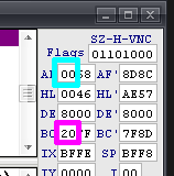
Flags:
SZ-H-PNC
|
||||||||||||||||||||||||||||||||||||||||||||||||||||||||||||||||||||||||||||
Command format
The format of Z80 commands is as follows
Command Destination,Source
and brackets () around a register pair like HL mean 'Address in register __'
so... LD (HL),A means "Load A into the address in HL"
Whereas.... LD HL,&4000 means "Load &4000 into HL"
and... LD B,A means "Load A into B"
Special Addresses on the Z80
There are some special addresses on the Z80 processor that are common to all Z80 systems.
The most important are:
RST0 ($0000 - Reset) which is usually the first command executed as the system restarts.
RST7 ($0038 - IM1 Interrupt) which is called by interrupts (Usually VBlank) in Interrupt Mode 1.
NMI ($0066 - Non Maskable Interrupt) is a special interrupt which can be caused by connected hardware, and cannot be turned off with DI.
Note: These may be 'ROM' on some systems (Like the SMS/MSX and ZX Spectrum). This will make using a custom interrupt handler in IM1 difficult or impossible.
The purpose of the NMI address ($0066) will differ depending on the system.
For Example: On the CPC and ZX Spectrum it's not typically used, however the Multiface II Stop button will cause an NMI interrupt (and a call to address $0066).
On the Master System the NMI is more important. an NMI interrupt occurs when the 'Pause button' is pressed on the console unit.
|
Address |
Purpose |
|---|---|
|
$0000 |
RST0: Reset |
|
$0008 |
RST1 |
|
$0010 |
RST2 |
|
$0018 |
RST3 |
|
$0020 |
RST4 |
|
$0028 |
RST5 |
|
$0030 |
RST6 |
|
$0038 |
RST7: IM1 Interrupt Handler |
|
$0066 |
NMI: Non Maskable Interrupt |
  |
The Gameboy is not a Z80, but it's similar in some ways...
however, the Gameboy 'GBZ80'
CPU has no IX or IY, and no shadow registers! We'll be covering the gameboy's weirdness more later! |
| The shadow
registers are a 'copy' of the main ones... on the CPC the system
firmware uses these during 'Interrupts' so you can't have them! But if we stop the interrupts then we can use them for even more power! Interrupts do things like read the keyboard and update the system - but we can replace the firmware and take over these jobs ourselves and take total control of the Z80 so we have all the power! |
|
Compare command and branches
| Basic command | Comparison | 6502 command | Z80 equivalent | 68000 equivalent |
| CMP Val2 |
CP Val2 |
CMP Val2,Val1 |
||
| if Val2>=Val1 then goto label | >= | BCS label | JP NC,label | BCC label |
| if Val2<Val1 then goto label | < | BCC label | JP C,label | BCS label |
| if Val2=Val1 then goto label | = | BEQ label | JP Z,label | BEQ label |
| if Val2<>Val1 then goto label | <> | BNE label | JP NZ,label | BNE label |

 |
You may want
to develop for the ZX spectrum or MSX, but you should start with
the CPC and WINAPE! Winape has a built in Assembler and Debugger that are second to none! In the early days you will make a lot of mistakes, and having the compiler , emulator and debugger in one place will save you a lot of time and problems! You can even develop MSX and SPECTRUM code with it - the MSX and Spectrum versions of ChibiAkumas are compiled in winape too!.... If you dont't use widows, Winape works OK with WINE! |
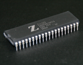
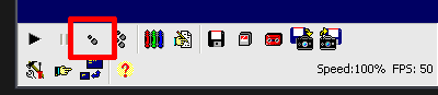
| To get started, Download Winape from this Link (I'm using V2.0b2) and extract it to a folder, | 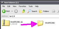 |
| Start Winape by clicking on the icon |  |
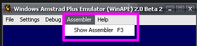
| You should see the emulator window
open and show the Amstrad CPC blue screen... the CPC starts
straight away into Basic... and the Amstrad CPC's basic is great
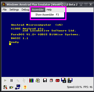
for testing ASM code! Don't worry if you've never used a CPC before, this tutorial assumes you know nothing about basic or the CPC! Now, Let's get straight into it and code something! Click on the Assembler menu and select "Show Assembler" - or press F3 on your keyboard! |
 |
| Select the File Menu, then New to create an empty ASM program | 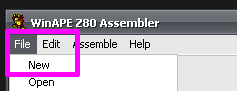 |
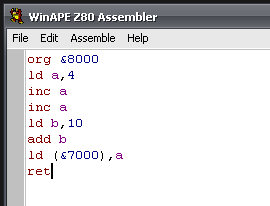
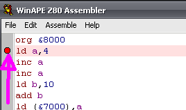
| We type in our ASM code into the
assembler. Note: Winape uses & to mark Hexadecimal symbols not $ Don't worry about the case as Winape isn't case sensitive.... ORG &8000 is the same as org &8000 |
 |
| Select Assemble from the Assemble menu to compile the program! | 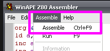 |
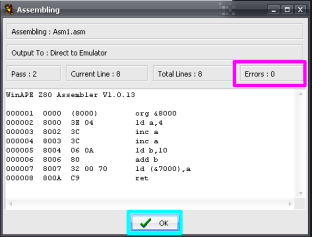
| You will see the Assembler output.
This shows the actual bytes of code that what you typed ends
up as! Check there are Zero Errors ... if there are then you've made a mistake typing! Click on OK! Now this is the magic of Winape - your code is now immediately in the emulators memory - so lets go run it! |
 |
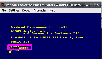
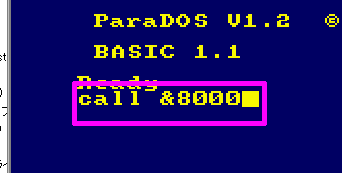
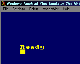
| Now go back to the blue screen...
and type in Call
&8000 and hit your enter
key Basic should return the message Ready if something else happened, check your code matches the screenshot above! What did it do? well we'll look at that in more detail next! |
 |
|
Congratulations!
You
just wrote and ran your first assembly program - and you now
officially Kick Ass! Now we'll look in detail at what the program did, and how to use Winape's debugger to look at it in detail! |
Now you've had a a quick go at assembly, lets look in detail at what that program does! We'll look at each line of the program, and explain what it means.
| org &8000 | ORG sets the ORIGIN of the code in memory - the Z80 has a 16 bit
address bus, so memory goes from &0000-&FFFF - but we
can't just use anywhere, as some bits are used by other things -
for example &C000-&FFFF on the CPC is used by the screen. &8000 is a good 'safe area' on the Amstrad for your code to start |
| ld a,4 | load A (the accumulator) with the number 4 - The Accumulator A is the main register used for calculations - registers are used for very short term memory storage |
| inc a | INCrease A by 1... A will now contain 5 |
| inc a | INCrease A by 1... hopefully you can guess it now contains 6 |
| ld b,10 | Set B to 10 ... B is another register... it can't do as much as A, but it can do a lot... notice the destination is on the left, and the source (the number) is on the right... this is always the case with Z80 assembly |
| add b | this adds B to A ... although A isn't mentioned in the command,
since the Accumulator A is used for almost all maths any time a
destination isn't mentioned, it will be A this command could be written as ADD A,B... winape will compile this, but the "A," is superfluous, so you're better off learning not to need it |
| LD (&7000),A | When Brackets () are used in assembly they define a MEMORY
location... &7000 is the a number (&7000) is the content
of that memory point! So this command puts A into memory location &7000! |
| RET | RET returns back to whatever called the program... in this case basic! |
Ok, we've read over the code, lets use the debugger to see the Z80 run the code!
| If you still have your assembler
open, just click on its window If you closed it, just click Show Assembler from the Assembler menu |
 |
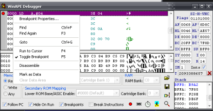
| Click
on the Grey Area next to the command "LD A,4" A red blob will appear! This means before the Z80 runs the command "LD A,4" it will stop, and the Debugger will appear! |
 |
| Select Assemble from the Assemble menu to recompile the program! | |
| Type Call &8000 again into basic, and hit Enter | 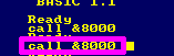 |
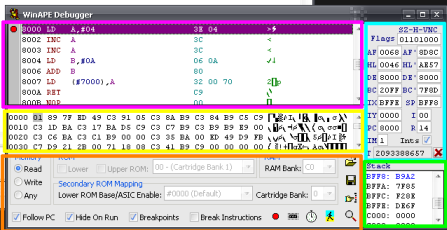
| If you've done everything right,
the debugger will immediately pop up! Lets take a look at what it
offers! At the top of the screen you can see the Compiled code... the line the Z80 is running is highlighted. On the Right you can see all the Registers - you should recognize the names! remember our code uses A and B... A is the first half of AF and B is the first half of BC In the middle of the screen you can see the Memory At the bottom of the screen you can see the Rom and other debugger options... don't worry about them now! In the bottom right is the Stack... we'll cover that very soon! |
 |
| The Debugger has tons of options
we're not going to use right now, but feel free to try them later!
Try right clicking on things for more options! You can even change the registers and memory by typing new values in! and remember - The worst you can do is crash your emulator, so there's no real harm you can do - so don't be afraid to mess! If you crash your emulator, the memory will be erased, so you'll have to re-assemble your code from the Assembler before Call &8000 will work again! |
 |
| Now Lets look at what your code
does! Press the F7 key on your keyboard (or the single step button on the main window) Keep an eye on the A and B registers in the debugger! |
  |
| You should see A change to 4... press F7 a few more times and watch what happens | 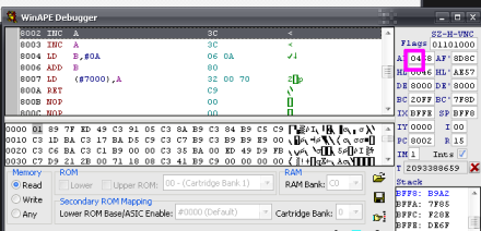 |
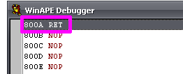
| keep pressing F7 again and again
until you get to the RET command! You can press it even more if you want, but remember... the debugger isn't just debugging your code, but the whole CPC... so you'll end up debugging the whole of basic! |
 |
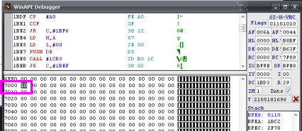
| When your code has finished running
we have one thing left to do.... Remember the program wrote to &7000 ? Scroll through the memory browser to find &7000 - and you should see our final value for A has been saved there! |
 |
| You can open the debugger by selecting Pause from the Debug menu at any time, or by pressing F7 - and just close it when you've seen enough and want your emulator to run normally! | 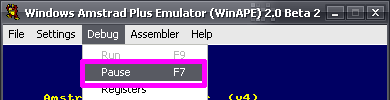 |
Think back on what you've just done, You've written a program, compiled it, run it, and watched everything the program did at the CPU level in more detail than you've probably ever seen any computer work before! Not bad for a days work! - and this is just lesson 1!
| Adding a few numbers may not seem much, but it's
just the start, and you'll soon find you can make the computer do
amazing thing! Also, don't forget, once you understand the basics, you can use pieces of other people's code to do the work you don't want to! These tutorials will show you how to build on the open source code of the Chibi Akumas game to allow you to make big progress super-fast! |
|
I highly recommend you type the programs in yourself, but you can download the source code with comments Here (Contains source for all lessons)
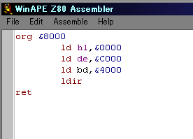
| Open up the assembler (Remember: Press F3 or select Show Assembler from the Assembler menu) Create a new document (File... New) Type in exactly what you see to the right!... there is a typo in this code - so we're going to have to debug it Once you've typed it in assemble it! (Ctrl-F9 or Assemble from the Assemble menu) |
 |
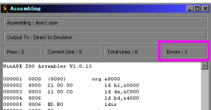
| Oh no! there's an error!... what a
surprise! Click OK to close the assembling window, and lets sort that error out! |
 |
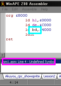
| The error that occurred will be
show at the bottom of the screen... double
click on it, and the cursor will jump to the error! Whoops, we've put BD ... theres no such pair! correct the error to BC Now reassemble the program, and you should get no errors! |
 |
| Type Call
&8000 and hit Enter |
 |
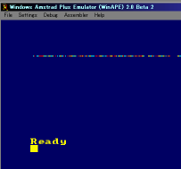
| The screen will clear, and the top
line or two will have some weird junk on it! |
 |
You probably think this is weird, but when we look at the code, This is exactly what we'd expect to happen... so lets break it down line by line!
| Our code is at &8000 - that's where we call to run it | org &8000 |
| Set HL to &0000 - in this case HL is a source memory address | ld hl,&0000 |
| set DE to &C000 - in this case DE is a Destination, and &C000 is the start of the CPC screen | ld de,&C000 |
| set BC to &4000 - in this case BC is a byte count - and &4000 is 16k, the size of the CPC screen! | ld bc,&4000 |
| LDIR means " Load, Increment Repeat"... in effect it copies BC
bytes from memory pos HL to DE |
ldir |
| return to basic | ret |
So we've copied 16k from &0000 to the screen - and what is at &0000 - well some system junk, and any basic programs!
don't believe me?... type:
10 print "moo"
Call &8000
and you'll see some more junk appeared! that new junk is your program as it appears in memory!
Of course if you set DE to &0000 and HL to &C000 - you'd copy the screen to your system area - and your machine will hang!
it will also hang if you set BC to &5000... why? well when the destination gets to &FFFF it rolls over to &0000 - again overwriting your system area - but give it a go if you want, there's no harm crashing an emulated machine!
| By
default
the CPC screen starts with &C000 at the 'top' but if you
make basic scroll up and down, the 'Top' will move somewhere
else, if you press the down cursor until the screen scrolls -
then call &8000 again you'll see the junk appear somewhere
else You can always reset the cpc by typing "Mode 1" in basic (reset to screen mode 1) |
|
|
If your crazy enough to try this on a
different system, you'd need to make a few changes, The ZX
Spectrum screen starts at &4000 not &C000, and the size
is &1800 On the MSX the screen isn't in memory so you can't see the effect on screen - and you'll crash the system if you write to &F000 or higher, but you could set the size to &1000, and see the change in memory between &C000-&D000 with a debugger if you want! |
 |
 |
Ok, you've had a quick look at LDIR,
Now lets try another more useful example,
| Type in the example code to the right, and assemble it as before | 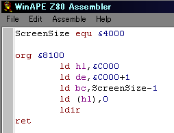 |
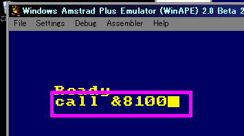
| Assuming you got no errors, lets
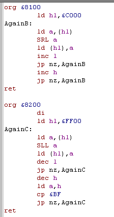
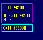
run the program. The ORG was different this time, so type Call &8100 |
 |
| The screen will clear! What's interesting is that this simple ASM code is faster at clearing the screen than the firmware's own CLS command!... and there's a lot of tricks we can do to speed it up even more... but we'll leave them for another day! |
 |
What did that code do? well lets break it down!
| This line defines a 'symbol' ... we're telling the assembler
'ScreenSize' EQUals &4000 A symbol is a constant in your code - basically every time the assembler sees 'ScreenSize' it will put in &4000 there's a couple of reasons to do this, firstly it's makes your code easier to read, and secondly, if you need to change it to &2000 - then you can just change this definition in one place, rather than all the places you've used it! |
ScreenSize equ &4000 |
| set the origin to &8100 (I'm using a different one, as all these examples are in the same 'lesson2.asm' in the download file) | org &8100 |
| Set the source HL to the start of the screen memory... yes, you read that right, the SOURCE | ld hl,&C000 |
| set the destination DE to one byte after the source... note that the assembler calculates what &C000+1 actually equals - not the Z80 | ld de,&C000+1 |
| set the Byte count to our defined symbol -1 (this will compile to ld bc,&3FFF) | ld bc,ScreenSize-1 |
| set the first byte of the source to 0 | ld (hl),0 |
| Run our LDIR copy... now here's the trick... at first LDIR copies the byte from HL (&C000 we just set to 0) to DE (&C001) next LDIR copies the byte from HL (now &C001 which IT just set to 0) to DE (now &C002) after that LDIR copies the byte from HL (now &C002 which IT just set to 0) to DE (now &C003)... and so on! We tricked LDIR into copying it's own data, and acting as a quick(ish) FILL command! |
ldir |
| return to basic | ret |
|
Mathematics in
ASM code in Winape code is pretty dumb... it can't do brackets
like 2*(5+1)... and it doesn't do multiplication first....
Usually you'd expect 5+1*2 to be equal 7... but in winape
this equals 12! Why? well winape does each command from left to right, so 5+1=6... then 6*2=12...it takes some getting used to, but it does work fine! |
Conditions and Loops!
We have one last version of this program to try!
| Type in the code to the right, and
compile it... you should get no errors. There's some new commands in here, but take a look at them in a minute! |
 |
| Type Call &8200 and hit enter | 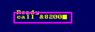 |
| The screen will do a strange
'fading clear'... Weird huh? Ok, it's not very useful, but it teaches us a lot of good stuff! |
 |
Lets take a look at the code, and see why it does what it does!
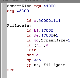
| Define our constant symbol "ScreenSize" as &4000 | ScreenSize equ &4000 |
| Start our program at &8200 | org &8200 |
| Set A to %00001111 - this sets all 4 pixels of a screen byte to cyan on the cpc screen | ld a,%00001111 |
| This is the definition of a label... it's like a the constant "screensize" in that the assembler converts future mentions of 'FillAgain' to a number when it compiles... however unlike 'screensize' that was defined with 'equ'... a label points to a memory location in the compiled code... if you take a look at the assembled code you'll see it is in the position &8202... that's because 'ld a,%00001111' takes 2 bytes |
FillAgain: |
| set HL to the start of the screen | ld hl,&C000 |
| set DE to one byte later (the same as last time) | ld de,&C000+1 |
| set BC to ScreenSize -1 ... you should recognize all this from last time! | ld bc,ScreenSize-1 |
| load the first byte with A - remember it will set all the pixels Cyan | ld (hl),a |
| Just like last time LDIR will fill the whole screen | ldir |
| Decrease A by 1 | dec a |
| Compare A with 255... when A=0 and we do DEC A... A will become 255... | cp 255 |
| if A does not match 255 , jump back to label 'FillAgain' The next command the Z80 will run will be 'ld hl,&C000' |
jp nz, FillAgain |
| Now you know how to do a loop! in fact JP Z
and JP NZ can be used like LOOPs, IF statements and even CASE
statements! Actually - you don't have a lot of choice as assembly has so few commands - but remember... all other programming languages compile down to Assembly - so anything Basic or C can do is possible in ASM - and ASM will always be fastest if you do it right! |
|
So we've used a Label, and a jump (JP) to create a loop!
there are three kinds of Jump command that you should know!
| Command | Meaning | Example |
| JP ## | This is like a GOTO command in basic, it will just jump to
the label or memory address you specify every time. this command takes 3 bytes |
JP &4000 |
| JP c,## | This is like an 'IF X THEN GOTO' command in basic. if
condition is met the jump will occur, otherwise program
execution will continue... there is no such thing as an ELSE, but
you can always immediately do another jump! this command takes 3 bytes |
JP Z,&4000 |
| JR # | do a Jump
Relative
to the current location... This is a bit tricky, but all you need to know is it takes 1 byte less than JP, but can only jump nearby - so it saves memory, but you can't always use it! |
JR label |
| JR c,# | Same as above, a 2 byte relative jump - saves one byte over JP c,## - but can't always be used if you need to jump far away | JR Z,label |
| djnz # | This is a special 'quick small loop' command... it
automatically Decreases
B and Jumps
if
b is NotZero DJNZ only takes up 2 bytes, so it's small if you only need a basic loop. a jr jump can only jump to a label that is nearby - so if you get an error use this alternative which can jump anywhere dec b jp nz,label |
DJNZ label |
| JP (HL) | Jump to memory location in HL, this is quite advanced, so don't worry about it now... but you can load HL with a label, then use this to perform a jump if you need to | JP (HL) |
So those are the Jumps we have available, but some of them need a condition too!...
we have 4 main conditions we need to so lets take a look at an example - you don't need to type it in
| load the accumulator with 4 | LD a,4 |
| Compare A to 10 | CP 10 |
There are 4 basic conditions we can use in this situation - it's annoying, but what the condition officially means, and what it does in this case are different
| Flag | example | Official meaning *** | Basic program equivalent | What it means when using CP |
| Carry | JP C,label | Carry is used with bitshifts and addition - if a byte goes over 255, it will go back to zero, but Carry will be True | A<CP | if A < CP Value then C is true and JP C,label will make the jump to label |
| NoCarry | JP NC,label | NC is true when there is no carry | A>=CP | if A > CP Value then NC is true and JP NC,label will make the jump to label |
| Zero | JP Z,label | Z is true when the last mathematical operation resulted in zero | A=CP | if A=CP then Z is true and JP Z,label will make the jump to label |
| NonZero | JP NZ,label | NZ is true when the last mathematical operation did not result in zero | A<>CP or A!=CP | if A<>CP then NZ is true and JP NZ,label will make the jump to label |
| Parity Odd | JP PO,label | Odd number of 1 bits | ||
| Parity Even |
JP PE,label | Even number of 1 bits |
||
| Sign Positive | JP P,label | Top bit (Bit 7) is 0 | ||
| Sign Minus | JP M,label | Top bit (Bit 7) is 1 |
 |
NC NC
Z and NZ don't make a lot of sense for < > = and
<> ... and they're a real pain to remember! Z and NZ are = and <> ... so try to think of them as 'is the difference Zero - or Non Zero?' C and NC are < and >= ... so think of them as Chibi (smaller) and NonChibi (bigger or equal) They're on the Cheatsheet, but if you can come up with a way of remembering which is which - all the better! |
|
|
Well
done!
You finished Lesson 2! But there's no reason to finish with
these programs if you don't want to! Try changing some of the numbers! What happens if you change 'ld a,%00001111' to 'ld a,%11110000' or 'ld a,%11111111', or change 'ScreenSize equ &4000' to 'ScreenSize equ &2000'... Have some fun! and try lots of things!... There's a video available describing more about how CPC & Spectrum screen memory work if you want to learn more now! |
|
| We're going to write a little
Assembly calculator Create a new assembly document, and type in the program to the right. Compile it - you should get no errors! You'll notice that the program takes it's input and output from 4 memory locations:
We're going to access these from a basic program - which we'll write now! |
 |
||||||||
| Type the program in to the right in
basic if you're not familiar with Basic, Don't worry about what the commands do, we'll look at them in a moment |
 |
| ADD and SUB
in assembly can add or subtract up to 255 from a register, but
if you only need to add or subtract one, use INC
or DEC, they increase or decrease a
register by 1... INC and DEC commands take only 1 byte, so they're faster than ADD and SUB... and they work on 16 bit registers like HL ADD and SUB only work on the 8 Bit Accumulator, but we'll learn how to do 16 bit equivalents later! |
|
|
CPC basic is
really easy, just start typing the lines in after the emulator
starts. If you make a mistake it's easy to fix- for example to edit line 30, just type "Edit 30" and hit enter! CPC basic also has a strange 'copy' command, which allows you to 'copy' text already onscreen... just hold down shift and use cursor keys to create a 'shadow cursor' and use Alt to copy the letters under the shadow cursor... on the CPC the 'Alt' key was marked 'Copy' |
 |
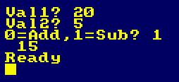
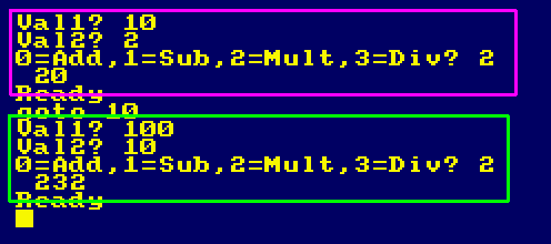
| Type RUN to start the program and
hit enter. Enter the values for the Variables as 20 and 5, hit enter after each value When asked if you want to Add or Subtract, Enter 1 for subtract The result will be show onscreen! |
 |
| Feel free to
try other values in the program, but it only uses 8 bit
registers, so it can only do up to 255, and can't do negative
values right! Right now it'll only do Addition and Subtraction because there aren't any built in Multiply or Divide commands on the Z80 - we're going to work around that next! |
|
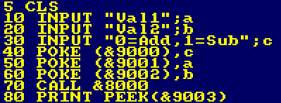
Lets take a look at the ASM code!
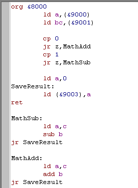
| program starts at &8000 | org &8000 |
| Read memory position &9000 into A | ld a,(&9000) |
| read two bytes into 16 bit register BC... on the Z80, 16 bit
registers are stored in memory in reverse So C is loaded from &9001 and B is loaded from &9002 |
ld bc,(&9001) |
| We want to do a 'Case statement' where we do different commands
depending on A, but no such command exists! No problem! we just do is lots of CP x commands and JR Z,label commands Remember, CP # always compares with A... and JR Z will do a jump if A matches with the compared value # |
cp 0 |
| Command 0 is add, so if this is what the user selected jump to the MathAdd label | jr z,MathAdd |
| Compare A to 1 | cp 1 |
| Command1 is subtract, so if this is what the user selected jump to the MathSub label | jr z,MathSub |
| if we got here, then A was something weird, so set A to 0 | ld a,0 |
| This is our SaveResult label, if a command was run then it will finish here, if the user put a strange number in, execution will also end up here | SaveResult: |
| Load the result (in A) to memory point &9003 | ld (&9003),a |
| return to basic | ret |
| The start of out subtract routine | MathSub: |
| we need our result in A, so load from C (Val1) into it | ld a,c |
| Subtract B (Val2) from A | sub b |
| we've finished, so Jump to our saveresult label | jr SaveResult |
| The start of our addition routine | MathAdd: |
| we need our result in A, so load from C (Val1) into it | ld a,c |
| Add B (Val2) to A | add b |
| we've finished, so Jump to our saveresult label | jr SaveResult |
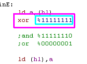
| Sometimes
in
ASM there's a smaller, faster command that has the exact
same result as another! For example, you can use "OR A" instead of "CP 0" "ADD A" instead of "SLA A"... and "XOR A" instead of "LD A,0" The result is identical, but you'll save some speed and memory!... it'll just look a bit odd in your code! It's something you'll want to learn to use.. so why not give it a try now! |
|
In case you're not familiar with CPC basic, lets take a look at the basic code!
| Clear the screen | CLS |
| INPUT asks the user a question, and stores the users response in
a variable So this will show "Val1?" onscreen, and store input from user into a Note: a/b/c in basic is nothing to do with A/B/C in ASM! |
INPUT "Val1";a |
| Show "Val2?" onscreen, and store input from user into b | INPUT "Val2";b |
| ask the user what command to run | INPUT "0=Add,1=Sub";c |
| POKE writes a byte into memory, this writes our command number into memory point &9000... this is how we'll get our values from basic to ASM | POKE (&9000),c |
| Store Value from A into &9001 | POKE (&9001),a |
| Store Value from B into &9002 | POKE (&9002),b |
| Call our ASM program | CALL &8000 |
| PEEK reads a byte from memory, allowing us to get the result our
ASM program produced. PRINT just shows it onscreen |
PRINT PEEK(&9003) |
|
Using
basic
to 'launch' and test your ASM code is a great way to develop
quickly and ease testing Using PEEK and POKE to get data to and from your program is a good solution, but you can also pass variables using the CALL command, but it's a little tricky, so we'll cover it later! |
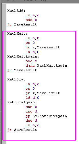
Multiply and Divide
We want to add Multiply and Divide commands, but unfortunately the Z80 does not have these commands! but we can simulate them by repeatedly using the ADD or SUBtract commands!
Add These Lines to the bottom of your code below MathAdd |
 |
| Add These Lines to 'case' condition block | 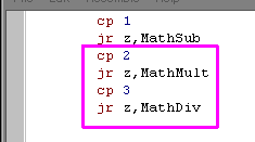 |
| use EDIT 30 to edit the line showing the options, make it the same as This | 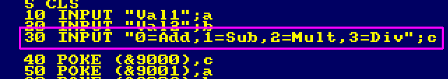 |
| You'll now be able to do multiplication, but only if the result is
less than 255! You'll also see that negative numbers don't work! If you try a number that ends up too high, or below zero, you'll get a strange number, that's because the numbers 'roll around' from zero back to 255 Later we'll upgrade the program to use 16 bit numbers, so we can go from -32768 to 32767! Take a look at the Hexadecimal tutorial at the start of this document if you want to know more about negative numbers now! You can get the source code for this lesson (and all the others) in the sources.7z file... the basic code can be found on the included disk image! |
 |
|
Repeatedly
adding or subtracting a number to 'fake' Multiplication or
Division is silly and slow, but if you only need to Double or
Halve a number you can use bit shifts... we'll cover them soon! You want to try avoid needing Multiplication and division if you can in your code, so design your game not to need anything except halving and doubling... of course you can do x4 or x8 by doubling twice or three times! |
| There are clever ways of doing Multiplication and Division that are much faster than this... but they are to complex to cover yet... but fear not - they're documented here when you're ready for them! | |
Lets suppose we have a value in A ... we need the value again later, but we need all our registers now too... what can we do? Well that's what the stack is for, it's a temporary store!
The stack is like a letter tray - we can put an extra sheet on the top of - and take it off later, but we can't get one from the middle, so we always get the Last one we put in - this is known as LIFO - Last in First Out
We use PUSH and POP to push a new item onto the stack, and pop it off later.
Lets look at two examples, and see why we want the stack!
Suppose we have a Call 'PrintChar' which will print the character in A ... and another call 'DoStuff' which will change all the registers - how can we keep A the same before and after this 'DoStuff' command? Well, we could save A to some temp memory - or let the stack take the slack!
don't type this in, it won't actually work!
| Without the stack ld a,'1' LD (Temp),a call PrintChar call DoStuff ld a,(Temp) call PrintChar Temp: db 0 |
With the stack ld a,'1' push af call PrintChar call DoStuff pop af call Printchar |
Both these do the same thing, but commands like LD (temp),a takes 3 bytes, and PUSH AF takes only 1.. and it's faster! also you no longer need that Temp: db 0 ... so that's another byte saved!
the stack always works in 16 bit - so even if you only want to save B - you'll have to PUSH BC - but don't worry , it's so fast you won't mind!
note: the F in AF is the 'Flags' (the Z NZ C NC in comparisons) - they're saved with A when you do a push.
You can push lots of different things onto the stack, but remember they will come out in the same order... you can even do PUSH BC then POP DE to copy BC into DE
| The
order
is important! if you're unclear on how the stack works, you
can use the Debugger in winape to step through your program,
and see what the stack does as your program works! seeing things happen step by step in the Z80 is a great way to see how things are happening |
|
| Lets do an example of the
stack! Type in the program to the right! |
 |
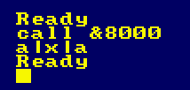
| Type Call &8000 and hit enter. The screen will 'Pause' so press A You should see A|x|A onscreen Run the program again, and press a different letter! |
 |
What was the point of that? well lets take a look at what the program does! I've colored the PUSH, POP commands so you can see what POP gets the matching value that was PUSHED
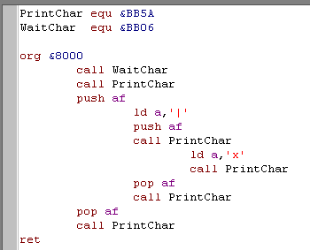
| This is a definition pointing at a command in the CPC firmware - it will print A to the screen as a character | PrintChar equ &BB5A |
| This is a definition pointing at a command in the CPC firmware - it will wait until a key is pressed and save it in A | WaitChar equ &BB06 |
| Start of the program at &8000 | org &8000 |
| Get a character from the user -this is why the screen paused - lets assume the user pressed A | call WaitChar |
| Print the character to the screen | call PrintChar |
| Push the character onto the stack - in this example 'A' | push af |
| Load a bar symbol into A | ld a,'|' |
| Push the bar onto the stack for later | push af |
| Print the bar to the screen | call PrintChar |
| Load an 'X' into A | ld a,'x' |
| Print the X to the screen | call PrintChar |
| pop an item off the stack... we will get the Bar we just pushed | pop af |
| Print the bar onto the screen | call PrintChar |
| pop an item off the stack, we get the character the user entered - in this example 'A' | pop af |
| print the character ('A') to the screen | call PrintChar |
| Return to basic | ret |
So we can push items onto the stack, and get them back later so long as we need them in the same order! But the stack doesn't just operate for us.. the Z80 uses it too
When we do a 'CALL label' command, the current running address is pushed onto the stack - effectively the Z80 does 'Push PC JP Label'
When we do a 'Ret' command... the Z80 effectively does 'pop PC'
Pc is the program counter - the current address the z80 is running... now this Push PC and Pop PC command don't really exist, but that's what the Z80 does - and you need to know this so you know why this program won't work:
| Command | What happens |
| Ld a,'Z' | Accumulator set to character 'Z' |
| push af | AF pushed onto the stack |
| Call ShowIT | the address of the next command (ret) is pushed onto the stack |
| Ret | end of the program |
| ShowIT: | |
| pop AF | we wanted to get 'Z' back - but we actually got the address of the command after Callit |
| call PrintChar | We wanted to print 'Z" but we actually printed half the address! |
| ret | we wanted to return from the call - but we stole that off the stack - return jumps to the AF value we pushed - and the computer will crash! |
|
If you don't
understand the stack yet, try making some test programs, or
editing the one you just typed in! The stack's used so much you'll see plenty of examples - and you'll soon get used to it! |
| The
stack
is the fastest way to read and write memory on the Z80 - if
you're clever you can use it in a 'tricky way' to quickly do
things like fill the screen. We'll learn how to do it later - it's an advanced trick, but if you want to make the Z80 as fast as possible - that's how to do it! |
|
Compiler Directives
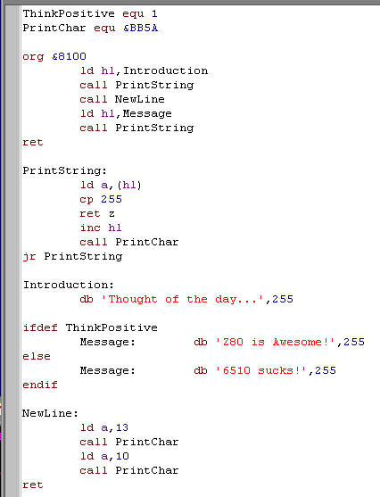
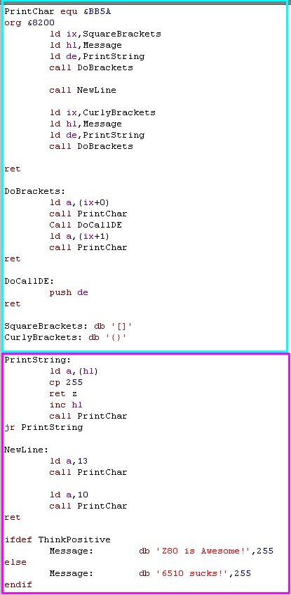
We'll move on from the stack - Lets have a look at another little program! - we're going to use the previous PrintChar command to make a string printing routine.
| Type in the program to the right. Assemble it - you should get no errors We'll explain what each line does after we run it! |
 |
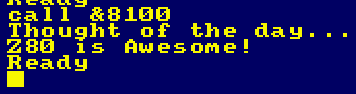
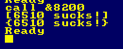
| Use Call &8100 to run the program It will print a little two-line message to the screen! |
 |
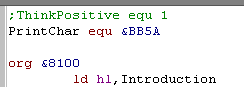
| Chage the first line - put a Semicolon ; at the start of it -
this marks it as a 'comment' - which means it does nothing in the
code Assemble it - you should get no errors |
 |
| Run the program again - The message has changed! | 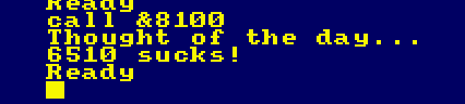 |
| Writing
somthing
as simple as a print string routine may seem a pain - and
you're probably wondering why the firware can't do it for you, But writing your own routines is the best idea - firstly - you'll know exactly what they do, and you can change them later to add special functions - and more importantly - you can port them to other systems and they will work the same! The less you use the system firware the better! your Z80 code will work the same on a CPC / Spectrum or MSX - firmware calls will not! |
|
That program probably seems rather long, but there's lots of good stuff in there! Lets take a look at it line by line!
| Define a symbol called 'ThinkPositive' and set it to 1 | ThinkPositive equ 1 |
| Define PrintChar, and point it to the memory address in the Amstrad Firmware that Prints ascii character A to screen | PrintChar equ &BB5A |
| Start of our program - the two lines above are instructions to the assembler, they do no compile to anything the Z80 sees | org &8100 |
| load the address of the Introduction string into HL | ld hl,Introduction |
| call our PrintString function | call PrintString |
| Call our NewLine function | call NewLine |
| Load the address of the Message into HL | ld hl,Message |
| call our PrintString function | call PrintString |
| Return to basic | ret |
| Start of out Printstring function | PrintString: |
| Load a Byte (character) into A from the address HL we were given | ld a,(hl) |
| Was the byte 255? | cp 255 |
| If it was (the difference is Zero) then we're reached the end of the string - so return to the calling program | ret z |
| increase the HL address counter | inc hl |
| call our PrintChar routine to show the letter in A onscreen | call PrintChar |
| Repeat the procedure. | jr PrintString |
| A label defining the address of our introduction message | Introduction: |
| a string of letters, ending with 255 - the assembler will convert these to their equivalent bytes according to their Ascii code. | db 'Thought of the day...',255 |
| remember that 'ThinkPositive' symbol? well we're telling the assembler that we only want to do the following if we've defined it! | ifdef ThinkPositive |
| A label 'Message' and a message that will compile when the IF statement above is true. | Message: db 'Z80 is Awesome!',255 |
| If 'ThinkPositive' is not defined (for example - when we put a semicolon in front of it) | else |
| A label 'Message' and a message that will compile when the IF statement above is false - Note: Normally you can't have two labels with the same name, BUT because the IF statement means only one will compile there ARE NOT TWO in the final program | Message: db '6510 sucks!',255 |
| End of the Assembler directive | endif |
| NewLine: | |
| A newline command | ld a,13 |
| Load Character 13 into A (Carriage return) | call PrintChar |
| Print it | ld a,10 |
| Load Character 10 into A (New Line) | call PrintChar |
| Print it | ret |
|
Feel free to
try other values in the program, It's important to note that the
IFDEF is actually changing the Compiled code - the 'message'
that is not shown DOES NOT EXIST in the compiled data! This allows you to compile multiple versions of your program - Chibi Akumas uses this to compile different builds of the game for CPC, ZX spectrum and MSX - and for different languages - all with one code base! |
The Indirect registers IX and IY
Suppose we have some bytes of data we want to read from a 'bank' of data - but we want to read those bytes by specifying an offset relative to the start address - we can use the Indirect register IX or IY to do this - lets look at an example
| Type in the program to the right,
and compile it. It's pretty long, but The bottom part is identical to your previously entered one, so just copy and paste it, from your last example - or just add the new code to the bottom of your old one. If it's too long, you can always download the sources file and just run it from there. |
 |
| Run the program by typing Call &8200 It prints a message inside two kinds of brackets |
 |
| Don't
underestimate calls from basic! A great way to make your first
game is to write the logic and input routines in basic, and call
out to assembly for things like drawing sprites and music! The important thing is the result you achieve, not the method - so why not make things easy for yourself and do some of the work in basic - you can always convert it to ASM later once you've worked out exactly what you need to do! |
|
Lets look at the program and see how it works!
| Start of the program | org &8200 |
| Load the Indirect register IX with the address of the square brackets | ld ix,SquareBrackets |
| Load the address of 'Message' into HL | ld hl,Message |
| load DE with the address of the Printstring function | ld de,PrintString |
| Call the DoBrackets function - we'll take a look at it in a second | call DoBrackets |
| Call the Newline command | call NewLine |
| Load the Indirect register IX with the address of the curly brackets | ld ix,CurlyBrackets |
| Load the address of 'Message' into HL | ld hl,Message |
| load DE with the address of the Printstring function | ld de,PrintString |
| Call the DoBrackets function - we'll take a look at it in a second | call DoBrackets |
| return to basic | ret |
| Start of the Dobrackets function | DoBrackets: |
| Load A from the address in IX (plus zero - so just IX) | ld a,(ix+0) |
| Print character A | call PrintChar |
| Run the function DoCallDE - we'll look at it in a moment. | Call DoCallDE |
| Load A from the address IX plus 1 - note this does not change the value in IX | ld a,(ix+1) |
| Print character A | call PrintChar |
| return from the subroutine |
ret |
| The function DoCallDE | DoCallDE: |
| Push DE onto the stack | push de |
| Return will take two bytes off the stack, and continue execution from that point - effectively we have done the command Call (DE) - the Z80 has no such command, but we have simulated it here | ret |
|
The
Chibi
Akumas game uses IX to point to the Player settings -
the Player routine gets the Life - position - health etc of
the player via IX+... references This allows the same routine to handle both players just by changing the IX reference when the function is called - the first time it points to Player1's data - the second time Player2's |
Call with parameters
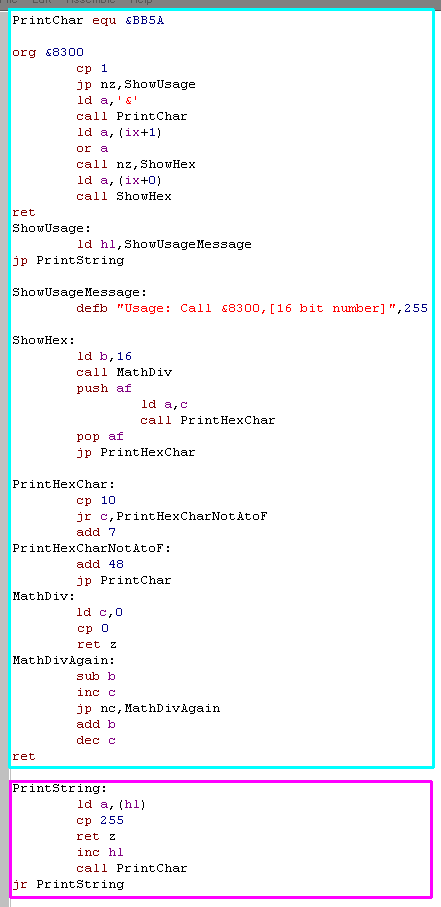
That example of IX was rather useless, but the IX register has a far more useful function on the CPC - we can use it to get data from the Call statement! Lets take a look at an example!
| Type in the example to the right -
it's rather long - if it's too much trouble, remember all the
examples are in the downloadable sources file. The Printstring function is the same as before - so you can just copy and paste it. |
 |
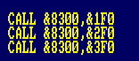
| Try typing Call
&8300 Because you didn't give a parameter You will see a 'usage message' Type Call &8300,12345 You will see '12345' converted to 16bit hexadecimal! Feel free to try it with some other numbers! |
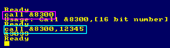 |
We've created a Decimal to Hexadecimal converter! and it gets its data straight from basic!
Lets take a look at the code and see how it works
| org &8300 | |
| When the program starts CPC basic will store the number of parameters passed in A | cp 1 |
| If the user did not pass 1 parameter, show how to use the program | jp nz,ShowUsage |
| Print an & symbol onscreen | ld a,'&' call PrintChar |
| Numbers are passed as 16 bit integers... The first parameter location is passed by basic in IX - because the data is passed in little Endian it's backwards, so we load the larger part from IX+1 into A | ld a,(ix+1) |
| if the high byte is not zero, call our ShowHex function | or a call nz,ShowHex |
| Load the smaller part from IX+0 (IX) int A | ld a,(ix+0) |
| Call ShowHex | call ShowHex |
| return to basic | ret |
| Show the usage message to the user - as the last command is a JP there is no need for a return command. | ShowUsage: ld hl,ShowUsageMessage jp PrintString |
| Message string we show the user if they used the program wrong | ShowUsageMessage: defb "Usage: Call &8300,[16 bit number]",255 |
| ShowHex function - this shows an 8 bit byte in Hex | ShowHex: |
| we want to Divide the number in A by 16 | ld b,16 |
| Call our Divide function | call MathDiv |
| The remainder is returned in A - we need it later - so we Push it now | push af |
| Load the result of the divide - this is how many 16's there were in the byte - so this is the first symbol in the hex string | ld a,c |
| Print the hex string | call PrintHexChar |
| get back A - this is now the second digit with a pop | pop af |
| jump to the PrintHexChar - because we don't use CALL there is no need for a return | jp PrintHexChar |
| This function prints a single hex digit 0-F | PrintHexChar: |
| Compare A to 10 | cp 10 |
| if A is less than 10 we need to print a digit. | jr c,PrintHexCharNotAtoF |
| Add 7 to A - this is the Ascii difference between 9 and A | add 7 |
| PrintHexCharNotAtoF: | |
| Add 48 (0) to the digit - this converts A to an Ascii character | add 48 |
| Print it | jp PrintChar |
| This mathDiv function is different from lastweeks, it stores the result in C and the remainder in B | MathDiv: |
| Reset C - it will store the result | ld c,0 |
| ifA is zero then return | cp 0 ret z |
| MathDivAgain: | |
| Subtract B from A | sub b |
| increase C (the result counter) | inc c |
| Repeat if we've not gone below zero | jp nc,MathDivAgain |
| we've gone over zero, so add b again, so A contains the correct remainder | add b |
| we've gone over zero, so decrease C to get the correct result | dec c |
| ret |
| Using
IX
is great - but it only works on the CPC - the MSX can pass one
variable (see the basic documentation) but other systems
cannot really do this - just use the POKE function in the
previous example instead! Other than CALL commands IX functions are great for settings data - you can use them for passing references to sets of data that you want to access and alter 'randomly' |
|
| Type in the program to the right, and compile it | 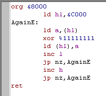 |
| Type in Call &8000, and see what happens |  |
| The screen colors will have gone weird! It's not clear what happened in 4 color Mode 1 Type in Mode 2... and Call &8000 again! |
 |
| Try changing the XOR to AND or OR Change %11111111 to other values like %11110000 |
 |
Lets take a look at what that does to Mode 2 - where each bit is a pixel!
| Sample | XOR %11110000 Invert Bits that are 1 |
AND %11110000 Keep Bits that are 1 |
OR %11110000 Set Bits that are 1 |
 |
 |
 |
 |
Lets see how that works at the bit level!
| Command | LD A,%10101010 XOR %11110000 |
LD A,%10101010 AND %11110000 |
LD A,%10101010 OR %11110000 |
| Result | %01011010 | %10100000 | %11111010 |
| Meaning | Invert the bits where the mask bits are 1 |
return 1 where both bits are 1 | Return 1 when either bit is 1 |
|
Each Bit is a
pixel in Mode 2 - but in Mode 1 it takes 2 bits the right half of the byte (%----XXXX) is color 1, the left half (%XXXX----) is color 2 - if both are set the result is color 3, eg (%00010001) will set the right hand pixel to color 3 It sounds weird, but just give it a try and see the results - and you'll soon understand it! |
Single Bit Operations
You can use NOT AND and OR to do operations on all the bits, but you need to use A - BIT SET AND RES can check, set and reset bits but can be used on other registers without affecting A
Lets give it a go!
| Type the program in to the right
and run it. If you remember from before, you'll know IX is used to get parameters. |
 |
| Switch to Mode 2 Try Call &8050,&40FF Also give Call &8050,&80F0 a go! The first part of the parameter must be &80 or &40 - but try other values for the second part! |
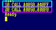 |
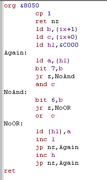
Lets take a look at the part of the program with new commands! we're going to skip over commands you should already know!
| You should understand this now! | org &8050 |
| Return if 1 parameter was not passed | cp 1 ret nz |
| Load the 'Operation' made up of the first two bytes of the passed parameter (eg XX in &XX--) - remember because of Little Endian these appear at IX+1 | ld b,(ix+1) |
| load the bitmask from the second two bytes of the passed parameter (eg XX in &--XX) | ld c,(ix+0) |
| You should understand this now! | ld hl,&C000 Again: ld a,(hl) |
| Check bit 7 of B (bit 7 is the far left - so this is like CP &80 or CP %10000000 - but CP would check A, and this works with B) | bit 7,b |
| If it was zero, jump to our label | jr z,NoAnd |
| use the AND command with parameter C | AND c |
| NoAnd: | |
| Check bit 7 of B (bit 7 is the far left - so this is like CP &40 or CP %01000000 - but CP would check A, and this works with B) | bit 6,b |
| If it was zero, jump to our label | jr z,NoOR |
| use the OR command with parameter C | OR c |
| NoOR: | |
| ld (hl),a | |
| ... |
Each bit number is a position from Right to Left
| Bit Number | 7 | 6 | 5 | 4 | 3 | 2 | 1 | 0 | |
| EG: | % | 1 | 0 | 1 | 0 | 1 | 0 | 1 | 0 |
There are 3 types of single bit commands, they can work on almost any register, where as AND %00000001 or OR %00000001 and CP %00000001 only work on A - and AND or OR will change A - these will not
| Command | SET b,r | RES b,r | BIT b,r |
| Meaning | Set Bit B in Register R | Reset bit B in register R | Check if bit B in register R is set |
| EG | SET 7,A | RES 6,A | BIT 5,A |
| Equivalent to | OR %10000000 | AND %10111111 | CP %00100000 |
| These commands
are great for using 'settings' variables where each bit has a
different meaning - In Chibi Akumas the pressed joystick buttons
are stored in a single byte and "BIT b,r" is used to test each
button. Things like object movements use different bits in a byte to allow a single byte to define all the possible move directions and types the game needs! |
|
Bit Shifting and Rotating
Sometimes we want to move the bits around in a byte, this can be be to double or halve a value, or to take a couple of bits 'out' of a byte via the carry.
| Lets try out the bit shifting
commands! Type in and compile these two examples! there are two versions because one is for shifting Right (&8100) and Left (&8200) |
 |
| Type Call &8100 and see what
happens! You'll want to see it run continuously, so type in a little basic program to repeat the process Try the Call &8200 version - and modify the program to Call &8200! |
 |
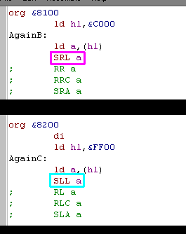
| Try replacing "SRL A" with "RR A" or "RRC A"
or "SRA A" - see what each does! Try replacing "SLL A" with "RLA" or "RLC A" or "SLA A" - see what each does! *** Note: SLL is an undocumented Opcode, and may not work on Z80 compatibles... For example it DOES not work on the eZ80 *** We'll take a look at them in detail in a second! |
 |
Carry Flag
So what do all those commands do? well first we need to understand the Carry Flag!
The Carry Flag is a single bit that stores the 'overflow' from 8 bit maths.
Question: What's 192 Plus 128?
Well in 8 bit maths - it's 64 - with a carry of 1... why? because, 8 bits can only count up to 255, and if there was a 9th bit it would be 1 - and the normal 8 bits would be 64 - confused? well lets take a look at it in binary
| Command | Carry | 7 | 6 | 5 | 4 | 3 | 2 | 1 | 0 |
| Ld a,192 | 0 | 1 | 1 | 0 | 0 | 0 | 0 | 0 | 0 |
| add 128 | 0 | 1 | 0 | 0 | 0 | 0 | 0 | 0 | 0 |
| (result) | 1 | 0 | 1 | 0 | 0 | 0 | 0 | 0 | 0 |
So the Carry allows us to store the 'overflow' from maths - and allows us to use 8 bit registers for 16 bits, or 16 bit register pairs for 32 bits... but they also allow us to do clever things with bits! Some commands use the carry to shift bits in and out of the register
Now lets take a look at what all those commands do!
| Result | Carry | ||
| Start Value | (Keep an eye on the colors to see how the bits move) | 10011001 | 0 |
| RR A | Rotates r right with carry - Carry is put at the left, right most bit is put in carry | 01001100 | 1 |
| RRC A | Rotates r right with wrap (Carry unused) | 11001100 | 1 |
| SRA A | Shifts r right, top bit is the same as previous top bit | 11001100 | 1 |
| SRL A | Shifts r right, top bit is set to 0 | 01001100 | 1 |
| RL A | Rotates r left with carry - Carry is put to the right, left most bit is put in carry | 00110010 | 1 |
| RLC A | Rotates r left with wrap (RLCA is actually faster) | 00110011 | 1 |
| SLA A | Shifts r left, bottom bit 0 | 00110010 | 1 |
| SLL A | Shifts r left, bottom bit 1 | 00110011 | 1 |
|
Shifting
bits
around can be used to change values in all kinds of ways -for
example shifting left doubles a value, Shifting right halves
it. You can do repeated bit shifts to take a byte apart, and load it into other registers, or reverse it. |
Self Modifying code
Lets change the subject a bit!
Remember the 2nd program? - it used a parameter passed by IX to decide what command to do?
The screen fill loop runs over 16,000 times, and using CP and Jump commands in that loop slows things down a lot!
What we really need is a way of comparing the parameter, and changing the action that takes no extra processing power... sounds impossible? well it's not... we make the program change its own code!
Because the program is in memory - and we can change memory, we can swap values or commands in our program whenever we want!
| Type in the program to the right
and compile it, If it's too much trouble, remember, you can always just get it from the sources file! |
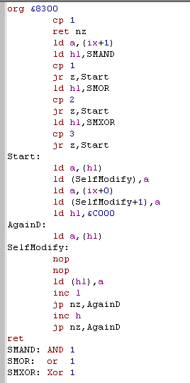 |
| Run the program with Call &8300,&xxyy Where xx is a command number from 01-03 , and yy is a bit mask from 00-FF You'll be able to see the result best in mode 2 |
 |
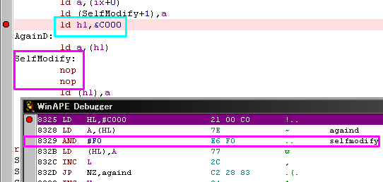
| Try putting a breakpoint in before
the loop (at ld
hl,&C000 , for example) Notice the NOP commands have disappeared and been replaced with a different command! (NOP means NO OPERATION - it does nothing and is just a placeholder) |
 |
Lets take a look at the new commands in the program, and see how it works!
| Check the user gave us 1 parameter | cp 1 ret nz |
| Load the first part of the parameter (&XX--) into A | ld a,(ix+1) |
| Load the address of our template AND command into HL | ld hl,SMAND |
| if A =1 then jump to the start | cp 1 jr z,Start |
| Load the address of our template OR command into HL | ld hl,SMOR |
| if A =2 then jump to the start | cp 2 jr z,Start |
| Load the address of our template XOR command into HL | ld hl,SMXOR |
| if A =3 then jump to the start | cp 3 jr z,Start |
| Start of the main program | Start: |
| Load the byte of the template command into A | ld a,(hl) |
| Write the byte to the label Selfmodify's address | ld (SelfModify),a |
| Load A from the second part of the parameter (&--XX) | ld a,(ix+0) |
| Write the byte to the one byte after label Selfmodify's address | ld (SelfModify+1),a |
| ld hl,&C000 | |
| AgainD: | |
| ld a,(hl) | |
| NOP is a one byte command that does nothing - these two bytes will be replaced by the self modifying code and the command and mask the user's parameter chose will be put here | SelfModify: nop nop |
| ld (hl),a inc l jp nz,AgainD inc h jp nz,AgainD ret |
|
| These three labels have a 'template command' which we pull the correct byte from to modify the code at 'SelfModify' | SMAND: AND 1 ;1 SMOR: OR 1 ;2 SMXOR: XOR 1 ;3 |
|
Different
commands have different bytes, so when using self modifying code
you need to know what bytes the commands compile to! In this example we've read from a 'template' command at a label - but it would be faster and save memory to just replace ld hl,SMAND with something like ld h,&E6 (&E6 is the AND command in this case) You'll never remember all the commands, but they're all on the cheat sheet, so just look them up when you need to! |
|
Self modifying code doesn't just allow you to make slow conditions fast, you can save memory with temporary variables.
For example, both these do the same thing:
| Normal: | Self Modifying: |
| ld a,(temp) inc a ld (temp),a ret temp: db 0 |
ld a,0 :SelfModVar_Plus1 inc a ld (SelfModVar_Plus1-1),a ret |
| Total: 9 Bytes | Total: 7 Bytes |
|
Self modifying
code is tricky, so don't worry about using it for now! One day you may want to make your program as fast and efficient as possible, and Self Modifying code will be waiting to do that for you! Just get used to the normal stuff and remember this as something you need to know about, even if you don't use it! |
This lesson's code is quite big, so you may just want to download it from the Sources file. We'll enter it in sections, and look at what each section does, then run it!
| Type in the code to the right You can't compile it yet, there's a lot more work to do! |
 |
| Copy-Paste the table below into
your code - (It's not an image!) Put it below the code you just entered! Seriously - you don't want to type all this in!!! |
| align
2 scr_addr_table: defb &00,&00, &00,&08, &00,&10, &00,&18, &00,&20, &00,&28, &00,&30, &00,&38;1 defb &50,&00, &50,&08, &50,&10, &50,&18, &50,&20, &50,&28, &50,&30, &50,&38;2 defb &A0,&00, &A0,&08, &A0,&10, &A0,&18, &A0,&20, &A0,&28, &A0,&30, &A0,&38;3 defb &F0,&00, &F0,&08, &F0,&10, &F0,&18, &F0,&20, &F0,&28, &F0,&30, &F0,&38;4 defb &40,&01, &40,&09, &40,&11, &40,&19, &40,&21, &40,&29, &40,&31, &40,&39;5 defb &90,&01, &90,&09, &90,&11, &90,&19, &90,&21, &90,&29, &90,&31, &90,&39;6 defb &E0,&01, &E0,&09, &E0,&11, &E0,&19, &E0,&21, &E0,&29, &E0,&31, &E0,&39;7 defb &30,&02, &30,&0A, &30,&12, &30,&1A, &30,&22, &30,&2A, &30,&32, &30,&3A;8 defb &80,&02, &80,&0A, &80,&12, &80,&1A, &80,&22, &80,&2A, &80,&32, &80,&3A;9 defb &D0,&02, &D0,&0A, &D0,&12, &D0,&1A, &D0,&22, &D0,&2A, &D0,&32, &D0,&3A;10 defb &20,&03, &20,&0B, &20,&13, &20,&1B, &20,&23, &20,&2B, &20,&33, &20,&3B;11 defb &70,&03, &70,&0B, &70,&13, &70,&1B, &70,&23, &70,&2B, &70,&33, &70,&3B;12 defb &C0,&03, &C0,&0B, &C0,&13, &C0,&1B, &C0,&23, &C0,&2B, &C0,&33, &C0,&3B;13 defb &10,&04, &10,&0C, &10,&14, &10,&1C, &10,&24, &10,&2C, &10,&34, &10,&3C;14 defb &60,&04, &60,&0C, &60,&14, &60,&1C, &60,&24, &60,&2C, &60,&34, &60,&3C;15 defb &B0,&04, &B0,&0C, &B0,&14, &B0,&1C, &B0,&24, &B0,&2C, &B0,&34, &B0,&3C;16 defb &00,&05, &00,&0D, &00,&15, &00,&1D, &00,&25, &00,&2D, &00,&35, &00,&3D;17 defb &50,&05, &50,&0D, &50,&15, &50,&1D, &50,&25, &50,&2D, &50,&35, &50,&3D;18 defb &A0,&05, &A0,&0D, &A0,&15, &A0,&1D, &A0,&25, &A0,&2D, &A0,&35, &A0,&3D;19 defb &F0,&05, &F0,&0D, &F0,&15, &F0,&1D, &F0,&25, &F0,&2D, &F0,&35, &F0,&3D;20 defb &40,&06, &40,&0E, &40,&16, &40,&1E, &40,&26, &40,&2E, &40,&36, &40,&3E;21 defb &90,&06, &90,&0E, &90,&16, &90,&1E, &90,&26, &90,&2E, &90,&36, &90,&3E;22 defb &E0,&06, &E0,&0E, &E0,&16, &E0,&1E, &E0,&26, &E0,&2E, &E0,&36, &E0,&3E;23 defb &30,&07, &30,&0F, &30,&17, &30,&1F, &30,&27, &30,&2F, &30,&37, &30,&3F;24 defb &80,&07, &80,&0F, &80,&17, &80,&1F, &80,&27, &80,&2F, &80,&37, &80,&3F;25 |
 |
If you want to
use this program on the Spectrum or Enterprise, you'll need a
different Look Up Table and Get Next Line routine!... and MSX
graphics are totally different, so you need to draw in a
different way. Don't worry, we'll get to it once we've learned all the Z80 commands - we're nearly done now! |
|
Reading from a Lookup Table
We can use a lookup table to read data from - in this case, our screen location contains 2 bytes, so we add the 'index' (ypos) twice to the start address, then rad in two byte.
The code you've entered coverts X,Y co-ordinates to screen locations - and calculates the position one pixel line down from the current memory location! this will be used to work out where our sprite will be drawn/read from, and to work through the sprite line by line
Aligned code
Aligned code is code that starts from a certain byte boundary - it is used for speeding things up, or look ups - by knowing where the data will start, we can save time by using INC L rather than INC HL - as we can know H will not need to change... the ALIGN command allows us to make assumptions about the position of the following code, without being as rigid as an ORG command
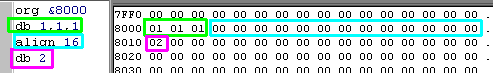
| Lets take a look at what the ALIGN command does In this example we have a few bytes of 1's defined with DB 1,1,1 The ALIGN xx command will align to the next xx boundary... in this case, it aligns to a 16 byte boundary The ALIGN 16 command inserts zeros as required. The DB 2 inserts a 2 - note it's aligned correctly! |
 |
|
Aligned code allows you to do all kinds of clever
things! A common trick is to define a 256 byte aligned table - with the "Mask" to erase the background when pixels are color 0 for every possible byte a sprite could contain - By setting H to the start of the table, and L to the byte - the mask can be applied by LD A,(HL) AND A It sounds confusing, but you'll soon think of lots of clever things you can use Lookup tables and Aligned code for! |
We can't run the code yet, because we're missing the sprite grabber - but lets take a look how it works!
| This is called a Jump block, it's allows us to jump to an
unknown location from a known one. Each JP xxxx command is 3 bytes, so we know "JP Get MemPos" is at &8006 - even though we don't know where "GetMemPos" is, we can use Call &8006 and it will have the same effect as Call GetMemPos - this allows you to write programs that can easily be called from basic, or other programs that were compiled separately! |
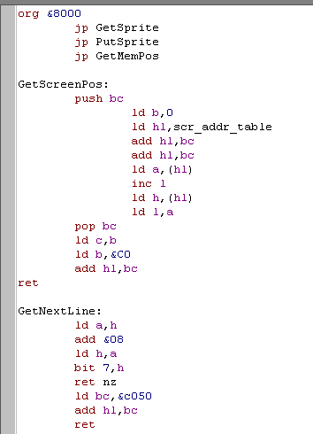
org &8000 jp GetSprite jp PutSprite jp GetMemPos |
| This command takes an X-pos in B , and a Y-pos in C, and
converts them to a screen memory location in HL note X is measured in BYTES - so there are 80 of them across the width of the the CPC screen - Y is measured in LINES |
GetScreenPos: push bc |
| Load the address of our LookupTable
for screen line memory locations We don't need the Xpos for now - so we set B to 0 Each memory location is 16 bit (2 bytes) so we add B twice to HL, this means HL points to data containing the 16 bit Memory location of the line we want - we just need to get at it! |
ld b,0 ld hl,scr_addr_table add hl,bc add hl,bc |
| We need to load HL with the data at the memory location IN HL -
first we load the low byte into A We use the faster INC L - not the slower INC HL because we used Align 2 - this means the data won't go over a 255 byte boundary (we know we're not on &80FF) - align will have added 0 bytes to ensure we're not. Then we load H from (HL) - don't worry! H doesn't get erased until AFTER (HL) has given us the byte we need! Then we load L from A - which we got the line before - and we're done! |
ld
a,(hl) inc l ld h,(hl) ld l,a |
| Get back BC - we want B (the xpos) to be in the low byte - and
we need to set the high byte to the position of our memory buffer
(&C0 - because the screen is at &C000) We add it to HL HL now contains the screen memory position of the X,Y pos we wanted! |
pop bc ld c,b ld b,&C0 add hl,bc ret |
| Finding the line below the current one is hard on most systems, On the CPC line tend to be &0800 below the last one, so we add &08 to H - which is faster than messing with HL | GetNextLine: ld a,h add &08 ld h,a |
| when we go over &FFFF we need to start back again at the top
- annoying isn't it? if the top bit is zero then we've rolled back to &0000 - but otherwise we're done |
bit 7,h ret nz |
| If we got here, then we rolled over, but we can fix things by adding &C050 - to get the correct position of the line! | ld bc,&c050 add hl,bc ret |
The next part of the program is the sprite grabber!
| Type in the program to the right! You still won't be able to compile it without the 3rd part! |
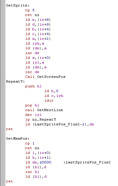 |
This routine grabs a sprite from the screen with "&8000,MEMDEST,X,Y,W,H" - and returns the next free MEMDEST with "Call &8006,@int"
Undocumented registers IXH, IXL,IYH,IYL
IX and IY are 16 bit register pairs like HL, they're actually made up of 2 registers we can use for whatever we want!
IX is made up of IXH (IX-High) and IXL (IX-Low)
IY is made up of IYH (IY-High) and IYL (IY-Low)
They aren't as fast as other registers - but there are times they are useful - in this example we use them as loop counters!
|
These
registers are undocumented - That means they weren't originally
in the Z80 manual - but all Z80's support them, they even work
on the MSX Turbo-R's R800 - so don't be afraid to use then! Back in the 80's people didn't know about them, so we can use them to give our programs a speed advantage over the old games! |
Basic References and 16- bit integers with @ and %
In CPC basic, putting @ before a variable will pass it as a 'reference' - this means we get the address of int, not the just value - and our program can change the value that the basic variable has! This allows us to store the memory location of sprites in integers in basic!
But make sure you specify they are integers by putting % at the end of the variable - otherwise they will be a floating point number, eg s1%=0 will define s1% as an integer.
| You can pass
other data types, but they're harder to use, as you need to know
how data such as strings and floating point numbers are stored
on the CPC 16-bit integers are easiest to work with, so make sure you put the % symbol at the end of the variable name! |
|
Lets take a look at how it works!
| Start of the sprite grabber - Check we were given 5 parameters | GetSprite: cp 5 ret nz |
| Parameters come in backwards - and are always 16 bit... so MEMDEST is at byte position 8 & 9 - this is where we will store the sprite | ld e,(ix+8) ld d,(ix+9) |
| X is at position 6, Y is at position 4 - we only expect 8 bits, so we ignore positions 7 and 5 - These are the screen position to grab from | ld b,(ix+6) ld c,(ix+4) |
| Load the Width from position 2 - store it in IYH, and also in
the destination memory Increase the destination memory pointer |
ld a,(ix+2) ld iyh,a ld (de),a inc de |
| Load the width from Position 0 - store it in IYL, and also in the destination memory | ld a,(ix+0) ld iyl,a ld (de),a inc de |
| Convert B,C to a screen memory pos | Call GetScreenPos |
| Back up the screen memory co-ordinate Set BC to the number of bytes we want to copy use LDIR to copy from the screen to DE |
RepeatY: push hl ld b,0 ld c,iyh ldir |
| Get back the screen memory pos, and move down one line | pop hl call GetNextLine |
| Decrease the line counter, and repeat if we're not at zero | dec iyl jp nz,RepeatY |
| Store the next empty memory position using self-modifying code | ld (LastSpritePos_Plus2-2),de ret |
| Check we were given one parameter | GetMemPos: cp 1 ret nz |
| Load the reference into HL | ld l,(ix+0) ld h,(ix+1) |
| Load DE with a value - note we're using self-modifying code - so the value will be the end of the last sprite | ld de,&0000 :LastSpritePos_Plus2 |
| Write the 16 bit value in DE to the memory position that HL contains | ld (hl),e inc hl ld (hl),d ret |
EX DE,HL - When HL just won't do!
HL has more power than anything else, but sometimes we want to use DE for the same job - well, we can't! but we can swap HL and DE quickly to do what we need - it's faster than any kind of PUSH POP options if you just need to swap the two - in this case it allows us to use LDIR to read from HL, and write to DE!
| One last bit to go! The PutSprite
routine... don't give up, the finish line is in sight! Type the code to the right! Compile it, you should get no errors! |
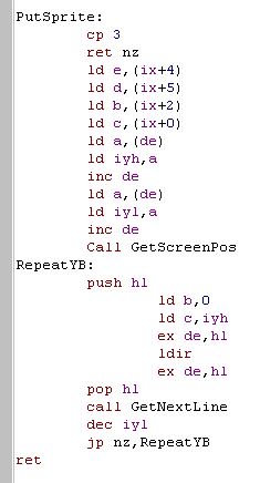 |
Now we can Grab sprites, and Print them to screen!
Here's a little Basic program to try it out!
| Type in the program to the right. It will define 3 sprites, one of 9 numbers (Stored in S1%) one of 9 letters (Stored in S2%) one is blank (stored in S0%) Run the program, it will show one of the sprites on screen! |
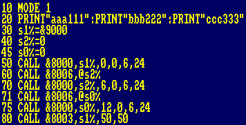 |
Lets see how our basic program uses the commands
| Reset the screen and print some letters to use as sprites | 10 MODE 1 20 PRINT"aaa111":PRINT"bbb222":PRINT"ccc333" |
| Define 3 variables to store the locations of our sprites - the %
symbol defines them as 16-bit integers Our sprites will start at &9000 - we'll work out the locations of the other two later |
30 s1%=&9000 40 s2%=0 45 s0%=0 |
| Grab (0,0)-(6,24) and store it at memory location in S1% | 50 CALL &8000,s1%,0,0,6,24 |
| Pass S2% by reference (the @ symbol denotes this) - our ASM program will put the next free sprite position into basic variable S2% - so we know where this sprite will start! | 60 CALL &8006,@s2% |
| Grab (6,0)-(12,24) and store it at memory location in S2% | 70 CALL &8000,s2%,6,0,6,24 |
| Get the Next sprite memory location, and store it in S0% | 71 CALL &8006,@s0% |
| Grab (12,0)-(18,24) and store it in position S0% | 75 CALL &8000,s0%,12,0,6,24 |
| Show sprite S1% at screen position (50,50) | 80 CALL &8003,s1%,50,50 |
Now you can make and use your own sprites from Basic!
| Need more inspiration? try adding
the basic code to the right! This will show a sprite on screen, and erase it - you can move the sprite with keys ZX K and M Don't let the sprite go off screen though! there's no checking and it may crash the CPC The basic program is on the Sources.DSK image! |
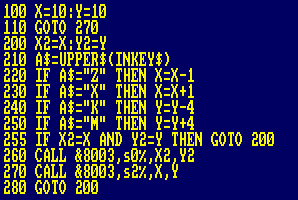 |
| INKEY$
reads a character from the keyboard, it's a quick easy way to
read input! In this example we use it to move a sprite around the screen! I'm sure you can think of more interesting things to do with the code in todays lesson! |
|
Vector Tables - Lookup tables for Jumps!
We can use the same code we just used in our look-up table for calling subroutines - we can take a 8 bit integer, and use it to decide on a Jump.
"CP X JP Z,YYYY " uses 5 bytes per command!
A Jump block uses 3 bytes for each command!
A vector table uses only 2 bytes per command!
If memory is tight, a Vector table is the best option... and a jumpblock does not get slower when working with a lot of entries - where as repeated "CP x.. JP Z,yyyy" commands will waste CPU power for each command skipped over to find the matching label
DW - defining 2 byte 16 bit 'Words'
We use DW xxxx to define a 16 bit word - we could do the same with 2 DB commands - but that would make no sense in this case
| Let's take a look at a vector table! Add another jump to the Jump block below JP GetMemPos |
 |
| Type in the program to the right
and compile it You can run it with Call &8009,x - where x is 0-2 This will call one of the commands in the VectorTable |
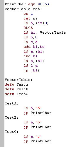 |
| if we ALIGN the vector table so all the commands are in the same byte boundary we can make the Vector table lookup simpler! | 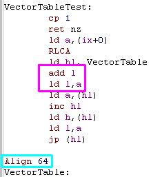 |
Lets look at how the Vector Jump works!
| Check we got 1 parameter, and load it into A | VectorTableTest: cp 1 ret nz ld a,(ix+0) |
| Rotate the bits in A left, effectively doubling it - we do this because each entry in our vector table is 2 bytes | rlca |
| Load our vector table into HL Set BC to the byte offset of the command we chose ADD BC to HL - HL now points to our command |
ld hl, VectorTable ld b,0 ld c,a add hl,bc |
| load HL with the address of a command from the VectorTable | ld a,(hl) inc hl ld h,(hl) ld l,a |
| Jump to the address in HL | jp (hl) |
| The vector table - each line is a 16 bit address of a command - the first will be called if the parameter is 0 | VectorTable: defw TestA defw TestB defw TestC |
RSTs and Interrupts in IM1
CALL commands take 3 bytes, but there is a special way the Z80 can do a limited call in just 1 byte! these call to an address in the first 64 bytes of the address space!
These are called with the commands RST 1 to RST 7 ... and they each call a different address - depending on the platform they may be in use, or have a special function. of course, if we don't need the firmware, then all bets are off, and we can do whatever we want with them!
Unfortunately because systems like the Spectrum and TI-83 have Read only Memory in the address range &0000-&3FFF - so we can't write our own RST's
The MSX Rom has predefined RST's, but if we page in RAM, then there are none defined
|
RST's
are only really useful when you need to do the same call or a
few commands a lot! Sometimes you'll see RSTx followed by a byte or two... (EG EXOS - rst6 on the MSX) The RST function will be looking at the stack, and reading in the 'calling address' to get the location of these bytes as parameters - then modifying the return address to skip over them! |
Lets take a look at the RST's on each system, with the firmware use of them
| Command | Equivalent Call | |
|
|
|
 |
 |
| RST 0 | Call &0000 | Reset | ROM - Reset | Rom:? Ram:free | reserved for CPM | Rom:? | Reset |
| RST 1 | Call &0008 | Low Jump | ROM - Unused | Rom:? Ram:free | free | Rom:? | Error Handler |
| RST 2 | Call &0010 | Side Call | ROM - Print Char | Rom:? Ram:free | free | Rom:? | Print char A |
| RST 3 | Call &0018 | Far Call | ROM - Get Char | Rom:? Ram:free | free | Rom:? | get Basic Char |
| RST 4 | Call &0020 | Ram Lam | ROM - Get Next Char | Rom:? Ram:free | free | Rom:? | get Basic Front char |
| RST 5 | Call &0028 | Firm Jump | ROM - Call Rom1 Routine | Rom:? Ram:free | free | Rom:Bcall | Floating point Calc |
| RST 6 | Call &0030 | free for user use | ROM - Unused | Rom:? Ram:free | EXOS call | Rom:? | Usr RST (RST30V) |
| RST 7 | Call &0038 | IM1 Interrupt Handler | IM1 Interrupt Handler | IM1 Interrupt Handler | IM1 Interrupt Handler | IM1 Interrupt Handler | IM1 Interrupt Handler |
| NMI Interrupt handler | Multiface II Button | NMI Interrupt handler | NMI Interrupt handler | NMI Interrupt handler | NMI Interrupt handler | NMI Interrupt handler |
The one we're really interested in here is RST7 at &0038 - because this one is called automatically by the system hardware when IM1 is enabled.
There will be times we need to do an event with controlled frequency, for example playing music, and to do that we use the 'Interrupts' of the system
Interrupts are when the hardware forces the Z80 to process tasks for it - and up until now we've just let the firmware do them itself, but now we're going to look at how to take them over ourselves
the commands IM0 - IM2 change the interrupt mode of the z80
IM1 is the most useful to us, IM0 is pretty irrelevant to us as programmers, but on the spectrum we can't write our own IM1 interrupt handler, as the rom stops us writing to &0038, but we can use IM2 - but it's more complex... so we'll look at that later!
Not only does writing our own interrupt handler and do 'timed' actions, but if we take over this task from the firmware, then we can be in control of all the Z80 resources - and this includes the 'shadow registers' that' we've not seen until now!
Shadow Registers
Now we've taken total control of the Z80 from the firmware - and we can use all it's registers without worrying about the effect on the firmware (unless we return to basic!)
This gives us access to the Shadow registers - the Z80's 'spare' set of the registers AF BC DE and HL - these are switched in by the firmware so that the main registers are not altered and the program can resume once the interrupt is done!
| Normal Registers | Shadow Registers | |||
| Accumulator | A | A' | ||
| Flags | F | F' | ||
| HighLow Memory Location | H | L | H | L |
| ByteCount | B | C | B | C |
| DEstinaton | D | E | D | E |
| IX | IXH | IXL | ||
| IY | IYH | IYL | ||
You'll notice that there are no shadow versions if IX or IY
| The
shadow
registers cannot be used in combination their normal
counterparts, instead we 'toggle' the shadow versions in or out
using two special commands which 'swap' the normal and shadow
versions. Of course we could just use PUSH and POP to get the same effect - but swapping the shadow registers is faster - which is why they exist, to allow the Interrupt handler it's own registers to quickly use without affecting normal ones! |
|
| Command | Effect |
| EX AF,AF' | Swap A and F with the shadow versions |
| EXX | swap BC,DE and HL with the shadow versions |
So we can swap just AF... or all the other main registers... because we can's swap just some of the 16 bit registers, if we just need to use one pair such as DE or HL for a while, PUSH and POP are better...
EXX only works when we need to use ALL the registers... so times when a separate job needs to be done for a while before carrying on with the main job may be the usage case of shadow registers.
For example In Chibiakumas this is used in the bullet loops, where the main registers are used for calculating bullet position, then the shadow registers are used for player collision detection, before switching back the main registers to continue the loop.
Interrupts
On the systems we're looking at interrupts only occur based on the screen refresh, but the frequency varies depending on the system, some systems need you to 'tell' the hardware the interrupt it's been processed otherwise it'll keep happening immediately again! - lets look at all the Interrupt facts by system so we know what we're dealing with for the systems we're interested in
| System | Interrupt frequency | HZ | If interrupt is missed | How to clear the interrupt | Firmware / Interrupt register usage |
|
6 times per screen draw (CPC+ can have line interrupts) |
300hz | Interrupt happens as soon as possible |
no need | All shadow registers used Shadow register BC' must not be changed or firmware will crash |
|
Once per screen draw | 50hz | Interrupt never occurs | no need | Shadow registers are not affected IY must be preserved for firmware to work properly (IY Should be &5C3A?) |
|
Once per screen draw | 50hz | Interrupt happens as soon as possible |
in a,(&99) (when chosen VDP status reg is set to default of 0) |
Shadow registers are not affected No registers need to be preserved |
|
Once per screen draw | 50hz | Interrupt happens as soon as possible |
ld a,30h out (0b4h),a |
Shadow registers are not affected No registers need to be preserved |
|
Various such as line based (port 249) (default Interrupt will happen once per redraw) |
50hz | interrupt never occurs | no need | Shadow registers are not affected No registers need to be preserved |
 |
Once per screen draw | 50hz (PAL) 60hz (NTSC) | Interrupt happens as soon as possible |
no need | No default interrupt handler Note &0066 is the NMI interrupt handler, which is executed when the pause button is pressed on the console |
|
Once per screen draw Non standard - address &0040 is VBLANK |
60hz | Interrupt never occurs? | No need | No default interrupt handler |
HALT, DI, EI
The Interrupts will occur automatically at the appropriate time, but we can wait for one to occur, by using the HALT command... this will cause the Z80 to wait for an interrupt to occur.
There may be times we cannot allow interrupts to occur - We can stop interrupts from being allowed for a while by using DI - and allow them again using EI...
On most systems if an interrupt is missed it will occur immediately, but on the Spectrum it never happens - see the table above for details.
|
There are many
times you may need to stop interrupts: if you're interrupt
handler uses the shadow registers and you need them... if you're
communicating with a series of OUTS that interrupts would
conflict with (Keyboard and sound chip are on the same CPC
ports)... Disabling Interrupts reduces the complexity of debugging too, so if you don't need them, you may as well disable them. Finally there's one special reason why interrupts can't run... If we've altered the stack pointer then the RST7 call cannot occur... we'll learn why you may decide to do that next time! |
Communicating with hardware - OUT and IN
Interrupts are the only time the hardware takes over the CPU - but there are times we need to give instructions to the hardware, or receive data from the hardware... and we use the commands OUT and IN to send data to the hardware.
If you think of the computer hardware as a telephone system, and each piece of hardware has a phone numbers from 0-255 (called a port)
OUT (xx),yy will call the hardware at number xx - and give it message yy
IN (xx),yy will call the hardware at number xx - and receive a message which will be stored in yy
Hardware you may access will be things like screen hardware, memory bank switchers, disk systems,joysticks and keyboards - the ports that you'll want to use, and how to use them varies depending on the system..
Now! there's a catch! The Z80 in the ZX spectrum, Sam Coupe and the CPC are wired oddly... they use 16 bit ports and use BC as the port number - even though the assembly command is Out (C) the command in the assembly code is not the one that effectively occurs when the Z80 runs it....
Even worse, some devices are listening to many ports, so OUT ing to &7F00-&7FFF on the CPC should have the same effect - usually one port is the 'recommended' one, and others just 'may' work (I had color changing code that sometimes worked fine, and other times corrupted disks)
Let's make this command confusion clear, or this will waste a load of your time!
| System | Command in ASM code | Command the system actually runs |
|
Out (C),A Out (C),C Out (n),A OTIR |
Out (BC),A Out (BC),C *** Does not work *** *** Malfunctions *** |
|
Out (C),A Out (C),C Out (n),A OTIR |
Out (C),A Out (C),C Out (n),A OTIR |
The Z80 has some 'incremental' commands for OUT like OTIR that are functionally similar to LDIR ... because these commands alter B, and B is used as the address of the OUT command these commands will malfunction...
On the Amstrad CPC we can use port &7F to control the screen colors - and because the CPC interrupt occurs 6 times a screen, by changing the color every interrupt, we can get more colors on screen than normally possible - This is how Chibiakumas gets around 8-10 colors on the 4 color mode 1 screen!
We're going to do this ourselves, in the next example
| Outs are
confusing and hard work! but you won't want to write them very
often! In practice what you'll do is write a function to control the hardware, then you'll forget about how it works and just use that function, so just find a good example online of what you need to do, and just stick to the safe code they use! |
|
Well, that was a lot of theory! but it all fits together into a really neat example!
| Type in the program to the right. Compile it, and run it by using Call &8000 Note, this example does not return to basic, so you will need to reset your emulator |
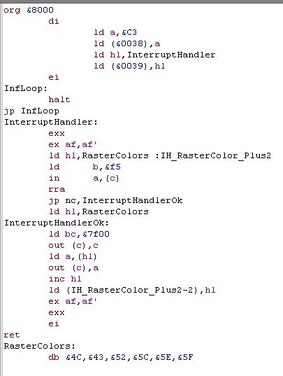 |
| This program will change the
background color each interrupt. You will see the background color change six times during the screen refresh! (the first one is offscreen!) |
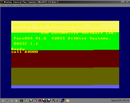 |
How does it work? well lets take a look at the code!
| org &8000 | |
| Turn off interrupts - We're going to mess with the interrupt handler, and need to make sure an interrupt doesn't occur while we do | di |
| set &0038 to &C3 &0038 (RST7) is the address called when an interrupt occurs, and &C3 is the bytecode of a JP command | ld a,&C3 ld (&0038),a |
| After the jump, we put the address of our code that will handle the interrupt | ld
hl,InterruptHandler ld (&0039),hl |
| Now we've finished setting up our interrupt handler, turn interrupts on! | ei |
| The HALT command waits for an interrupt, but this loop is just an endless loop.... we can't return to basic, because our interrupt handler will break basic! | InfLoop: halt jp InfLoop |
| When an interrupt occurs the Z80 will end up here... note interrupts are automatically disabled when &0038 is called | InterruptHandler: |
| swap HL,DE and BC with the shadow versions - we can now use these in our interrupt handler without worrying | exx |
| swap AF with the shadow version | ex af,af' |
| Load the address of our Rastercolors list - we're going to selfmodify this, so we have a label at the end | ld hl,RasterColors :IH_RasterColor_Plus2 |
| We want to check if the screen has finished redrawing - we can do this by accessing the 'PPI' port B... rather strangely this is connected to ports &F500 to &F5FF so we do not need to set C for this | ld b,&f5 |
| read A from port (BC) (CPC/ZX are 16 bit so use (BC) ... MSX/ENT are 8 bit, so use (C) ) | in a,(c) |
| Bit 0 is marks 'Vsync' so push the rightmost bit into the carry if it's zero, just carry on |
rra jp nc,InterruptHandlerOk |
| if we got here, then we're vsyncing, so reset HL to the start of the array | ld hl,RasterColors |
| Set B to &7F this is the Gate
array address set C to &00 - when we do OUT (BC),C this tells the gate array 'I want to change Color 0' |
InterruptHandlerOk: ld bc,&7f00 out (c),c |
| Read A from the HL Effectively performs - Out (BC),A - sends a palette color to the Gate Array to set Color 0 to |
ld a,(hl) out (c),a |
| Increase HL and remember the next address we want to read from using selfmodifying code | inc hl ld (IH_RasterColor_Plus2-2),hl |
| Restore the normal registers, and
turn interrupts back on Return to whatever was happening when |
ex af,af' exx ei ret |
| The 6 colors we will use for the screen - note these are not the usual 'Basic colors' you'll be used to - these are Hardware Colors! | RasterColors: db &4C,&43,&52,&5C,&5E,&5F |
|
We need to
take more care if we need to keep basic and the firmware happy! You'll need to do return to basic, or use firmware calls for screen operations - or disk access! On the CPC we need to keep the interrupt handler we replaced, and back up shadow register BC' - the the firmware will be OK |
Now lets take a look at how to change all the colors, and this time we'll do some screen changes in between interrupts - and we'll back up everything so we can return to basic!
| Type in the example to the right Compile it, and run with Call &8000 This example will flip the screen colors 10 times, then return to basic |
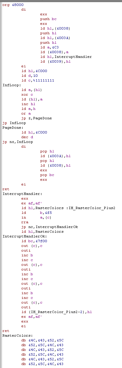 |
| This version will change all 4 screen colors, at all 6 raster points - and returns to basic as if nothing had ever happened! | 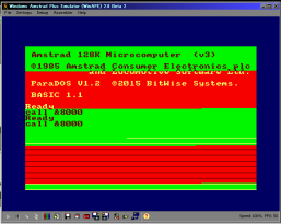 |
|
We
can only easily change colors at these 5 points... Drawing each line of the screen takes 64 ticks/cycles... if you want to change color each line, or on a specific line, you need to delay the processor with enough NOP's to get to the line you actually want! |
| Turn off interrupts while we're messing with the interrupt handler | org &8000 di |
| Back up BC' from the Shadow
registers - The CPC firmware relies on this being intact While the CPC firmware uses HL DE and AF in the shadow registers - it doesn't mind us changing them so we don't back those up |
exx push bc exx |
| Back up the first 4 bytes of the current interrupt handler so we can remove our changes later | ld hl,(&0038) push hl ld hl,(&003A) push hl |
| Set up our custom interrupt handler and turn on interrupts | ld a,&C3 ld (&0038),a ld hl,InterruptHandler ld (&0039),hl ei |
| Set our pointer HL to the start of the screen We use D as a loop counter - starting at 10 set C to %11111111 - we use this as our XOR mask |
ld hl,&C000 ld d,10 ld c,%11111111 |
| XOR each byte in the screen with the mask in C - when we finish the screen we jump to PageDone | InfLoop: ld a,(hl) xor c ld (hl),a inc hl ld a,h or a jp z,PageDone jp InfLoop |
| Reset HL to the &C000 (the
start of the screen) Decrease D and repeat until it's zero |
PageDone: ld hl,&C000 dec d jp nz,InfLoop |
| Turn off interrupts | di |
| Restore the Firmware default interrupt handler that we backed up before | pop hl ld (&003A),hl pop hl ld (&0038),hl |
| Restore Shadow register BC' | exx pop bc exx |
| Turn Interrupts back on and return! Basic will never know what happened!!! |
ei ret |
| Start of the interrupt handler Switch to the shadow registers |
InterruptHandler: exx ex af,af' |
| The same as last time! Set HL to color array (this will be self-modified) see if we're at the top of the screen, and if we are, reset HL |
ld hl,RasterColors :IH_RasterColor_Plus2 ld b,&f5 in a,(c) rra jp nc,InterruptHandlerOk ld hl,RasterColors |
| Tell the Gate Array at &7Fxx that we want to set color 0 | InterruptHandlerOk: ld bc,&7f00 out (c),c |
| OUTI will copy one byte from HL, and INC HL unfortunately it also decreases loop counter B - which will cause problems on the Amstrad - so we do INC B to fix it... even with the 'INC BC'... it's still faster than the separate commands! |
outi inc b |
| Increase C, and do another OUT - this tells the Gate array we want to do the same to Color 1 | inc c out (c),c |
| Do the same for Color 1,2 and 3 A loop counter and a jump would take a bit of time - and this is going to run 300 times a second! so actually have the same commands 4 time rather than using a loop to save some speed! ... this is called 'unwrapping a loop' |
outi inc b inc c out (c),c outi inc b inc c out (c),c outi |
| Remember the next address we want
to read from. Swap the shadow and normal registers back, Enable interrupts and return. |
ld (IH_RasterColor_Plus2-2),hl ex af,af' exx ei ret |
|
We're totally
kicking ass now! We've now learned how to communicate with the hardware ports, we've made our own interrupt handler, and we've learned how to use the 'Shadow Registers'... We've now learned almost all the Z80 commands! There's not much left to learn before we know everything! |
Lets take a look at the remaining commands the Z80 has that you may wish to know!
The last two Registers!
There are two registers left that we've not looked at, they have limits, but they may be useful in some cases!
The first one is R... this is used by the system to 'refresh' the memory to keep the data ok in ram... now you should not change this register, because it could cause damage to the memory, buy you can read from it fine - it will have a value in it from 0-127... and as it constantly changes it may be useful as a random number seed!
The other is I... this is used by Interrupt Mode 2 (IM2) - but unless you're using the ZX Spectrum you'll be using IM1, and it does nothing in IM1 - so I is free for you to do whatever you want...
Unfortunately there are only 2 commands, one to load A into I, and another to load I into A ... but it's faster than PUSH and POP - so if you want, you can use it for temporary storage!
|
The I register
isn't a lot of use as a general register, and you'll need it for
interrupts if you end up using the Spectrum. In Chibiakumas, The I register is used on systems except the spectrum... an assembler 'Macro' replaces LD I,A with a ld (&xxxx),a command on the spectrum - it takes a little extra memory, but means the spectrum version works without the I register for storage. |
DAA and Binary Coded Decimal
Converting 16 bit bytes for screen display is hard, and sometimes you may wish to just use 'Binary Coded Decimal'...
This is where each byte only stores a number
from 0-10... this is how ChibiAkumas stores the player score, there are 10
bytes for each of the 10 digits, this makes showing the score quick and
easy.
DAA is a strange command I've never had need to use, it's very complex, and you should look at the Zilog manual if you want to really know about it... the main people actually use it is nothing to do with Binary Coded Decimal, but in fact to convert a byte with a value of 0-15 to a hex char using the sample below
there are two other even stranger commands! RRD and RLD, I've never used them, and I can't think why you would, but here they are!
Carry Flag
There are some commands which do maths which will also use the Carry flag, this allows mathematical operations to include overflow from previous calculations. There are 8 bit and 16 bit commands, lets take a look at them, Rather strangely the only 16 bit subtract command is with carry - there is no SUB HL,DE!!!
As mentioned there is no way to subtract without the carry, so there may be times we need to set or clear the carry flag... another time will be if we want to use the Carry as a status flag - eg some disk routines set the carry flag if reading worked, and clear it if it failed.
There are two commands
I bet you thought CCF would clear the carry flag, well it doesn't! but
there is an easy way to clear the carry flag! just use
Alternatively, you can just convert a positive 16 bit number into a negative one, with the following code!
Return from interrupts with RETI and RETN
There are two 'Special' interrupt return commands RETI and RETN... to my knowledge there is no benefit to using these and they have no practice use on any system I know.
Bulk copy and search
We looked before at LDIR, but there is an alternative, LDDR - this version of the command is for use when HL is pointing to the END of the range you want to copy
Rather than copying, there are two 'search' commands, which will scan BC bytes from HL to find byte A ... I have never used them, but maybe I'm missing something!
Lets summarize all those commands
Special OUT and IN commands you'll probably never need!
There are a few special bulk IN and OUT commands, however as before, because BC is used as the port address on Amstrad and Spectrum, they may not work, and I doubt you'll ever need them, but here they are!
Stack Specials!
The stack has a couple of special commands, that may help if you're being tricky (Stack misuse - covered soon), some we'll use in a moment, but there's a couple that you should know
Some commands only work with a certain selection of registers, so check the Cheatsheet to see the full range of 'options' available!
Now, lets move on to the lesson!
Unwrapped Loops!
There are times when we need as much speed as possible, especially when we're drawing to screen... When we loop around a command like LDIR a lot of time is wasted with compare and jump commands, If we have enough memory to spare - we can jump less, and copy more data - lets take a look!
First lets create a 'slow' version with a regular LDIR command - this program will copy the whole screen TO and FROM a 128k memory bank
Most of this should be pretty clear to you by now, but lets have a look at that Bankswitch Command!
on the CPC there are 8 possible bank configurations, &C0 is the default, where the main 64k are in memory.... the other options are shown below:
Speed Up!
Now let's unwrap the loop... We're going to make a few changes, and make it faster!
Lets try this faster version we use 16 LDI commands - by skipping the R (repeat check) for most of the commands we can increase speed by around 25%!
There's not much to look at here, the only thing to note is that LDI, or LDIR set the PO flag to true when BC=0... Note, BC must be a multiple of 16, or this program will miss the 'return' and overwrite all the memory!
Stack Misuse!
There may be times when we need to read or write data super quickly... and there's a clever trick for this... as mentioned before, the Stack pointer offers the fastest reading and writing the Z80 can offer.
As we know the Stack pointer is designed for PUSH and POP, and for CALL's, but if we don't need to do any of these things, we can temporarily alter the stack pointer, and use it to bulk read, or bulk write a block of data super quick!... of course, Interrupts are a call to &0038 - so we'll have to disable interrupts to be safe! (Depending on what you're doing, you MAY be able to allow interrupts - eg if you're only writing... a few bytes would be temporarily corrupted by the interrupt handler's calls and pushes - though there are complex tricks to avoid this)
We've done some tricky stuff, so lets take a look!
This ends the Basic series.. but the lessons are just beginning!... Tune in next week for more Z80 fun!
Appendix
Note, as the Accumulator does most mathmatical operations you can just
enter ADD 4 ... but ADD A,4 has the same meaning... the shorter form will
be used in my guide
Note, On the CPC,Sam Coupe and ZX Spectrum due to the way the Z80 is wired OUT commands do not work as stated... OUT (C) will actually do OUT (B).. making commands like OTIR that use B as a counter likely to cause hardware problems (It caused random disk writes to me!)... OUT (#) will not work at all... OUT works normally on he MSX OUT (C) will do Out (C) and Out (#) works as stated
DAA is a strange command I've never had need to use, it's very complex, and you should look at the Zilog manual if you want to really know about it... the main people actually use it is nothing to do with Binary Coded Decimal, but in fact to convert a byte with a value of 0-15 to a hex char using the sample below
| This code will show A onscreen as Hex where A is below 16 | daa add a,&F0 adc a,&40 call PrintChar |
there are two other even stranger commands! RRD and RLD, I've never used them, and I can't think why you would, but here they are!
| RLD | Rotate Left 4 bit nibble at Destination (HL) using bits 0-3 of A as a carry |
| RRD | Rotate Right 4 bit nibble at Destination (HL) using bits 0-3 of A as a carry |
Carry Flag
There are some commands which do maths which will also use the Carry flag, this allows mathematical operations to include overflow from previous calculations. There are 8 bit and 16 bit commands, lets take a look at them, Rather strangely the only 16 bit subtract command is with carry - there is no SUB HL,DE!!!
| SBC # | SBC 4 | Subtract a (4+Carry) from A |
| SBC r | SBC B | Subtract (B+Carry) from A |
| SBC rr,rr | SBC HL,DE | subtract (DE+Carry) from HL |
| ADC # | ADC 4 | add (4+Carry) to A |
| ADC r | ADC B | add (B+Carry) to A |
| ADC rr,rr | ADC HL,DE | add (DE+Carry) to HL |
As mentioned there is no way to subtract without the carry, so there may be times we need to set or clear the carry flag... another time will be if we want to use the Carry as a status flag - eg some disk routines set the carry flag if reading worked, and clear it if it failed.
There are two commands
| SCF | Set the Carry flag (to 1) |
| CCF | Complement Carry Flag - inverts the carry flag |
| OR A | reset the carry flag |
Alternatively, you can just convert a positive 16 bit number into a negative one, with the following code!
| Convert DE into a negative number,
then add it to HL This will have the effect of subtracting DE from HL |
ld a,d cpl ld d,a ld a,e cpl ld e,a inc de add hl,de |
Return from interrupts with RETI and RETN
There are two 'Special' interrupt return commands RETI and RETN... to my knowledge there is no benefit to using these and they have no practice use on any system I know.
Bulk copy and search
We looked before at LDIR, but there is an alternative, LDDR - this version of the command is for use when HL is pointing to the END of the range you want to copy
| RETI | Return from an interrupt |
| RETN | Return from nonmaskable interrupt |
Rather than copying, there are two 'search' commands, which will scan BC bytes from HL to find byte A ... I have never used them, but maybe I'm missing something!
Lets summarize all those commands
| LDDR | same as LDIR, but HL goes down not up |
| CPI | Search from HL, increasing HL for BC bytes - try to find A, PO set if found |
| CPD | Search from HL, decreasing HL for BC bytes - try to find A, PO set if found |
Special OUT and IN commands you'll probably never need!
There are a few special bulk IN and OUT commands, however as before, because BC is used as the port address on Amstrad and Spectrum, they may not work, and I doubt you'll ever need them, but here they are!
| IND | In to HL and decrease HL |
| INDR | In to HL and decrease HL and repeat |
| INI | In to hl and Increase HL |
| INIR | In to hl and Increase HL repeat |
| OUTD | Out from hl and Decrease |
| OTDR | Out from hl and Decrease and repeat |
| The INI
command may be useful for reading from something like the
Keyboard into a buffer... just remember that it decreases
B each time you use it, and the Amstrad and Spectrum won't like
that one bit! if you use it in a loop, you'll need to reset B, or do an INI, then an INC B and everything should be fine! |
|
Stack Specials!
The stack has a couple of special commands, that may help if you're being tricky (Stack misuse - covered soon), some we'll use in a moment, but there's a couple that you should know
| INC SP | increase the stack pointer - do this twice instead of a POP (it's actually slower - but if you don't want to alter your registers) |
| DEC SP | decrease the stack pointer |
| EX (SP),HL | Swap the contents of HL with the item at the top of the stack |
Some commands only work with a certain selection of registers, so check the Cheatsheet to see the full range of 'options' available!
Now, lets move on to the lesson!
Unwrapped Loops!
There are times when we need as much speed as possible, especially when we're drawing to screen... When we loop around a command like LDIR a lot of time is wasted with compare and jump commands, If we have enough memory to spare - we can jump less, and copy more data - lets take a look!
First lets create a 'slow' version with a regular LDIR command - this program will copy the whole screen TO and FROM a 128k memory bank
| Type the program in to the right. It gives you 2 commands Call &8000,xx - will copy the screen TO bank xx Call &8003,xx - will restore the screen FROM bank xx xx should be a CPC bank number from C4-C7 or C0 ... other banks may work if you know how CPC banks work!!! Note, This program will not work right on a CPC464 - as these banks only exist on 128k systems, all the commands will copy to the same bank! |
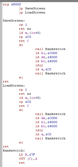 |
Most of this should be pretty clear to you by now, but lets have a look at that Bankswitch Command!
| This Bankswitch command will send a Bank number to the Gate
array The gate array is at &7Fxx... |
Bankswitch: LD B,&7F OUT (C),A ret |
on the CPC there are 8 possible bank configurations, &C0 is the default, where the main 64k are in memory.... the other options are shown below:
| C0 | C1 | C2 | C3 | C4 | C5 | C6 | C7 | |
| 0000-3FFF | RAM_0 | RAM_0 | RAM_4 | RAM_0 | RAM_0 | RAM_0 | RAM_0 | RAM_0 |
| 4000-7FFF | RAM_1 | RAM_1 | RAM_5 | RAM_3 | RAM_4 | RAM_5 | RAM_6 | RAM_7 |
| 8000-BFFF | RAM_2 | RAM_2 | RAM_6 | RAM_2 | RAM_2 | RAM_2 | RAM_2 | RAM_2 |
| C000-FFFF | RAM_3 | RAM_7 | RAM_7 | RAM_7 | RAM_3 | RAM_3 | RAM_3 | RAM_3 |
|
If
you have more than 128k, you will have options C8,C9 and so
on... up to FF if you have 512k! Note, you cannot use &C2... this swaps out &8000 - which is where your program is, so it would cause a crash! |
Speed Up!
Now let's unwrap the loop... We're going to make a few changes, and make it faster!
Lets try this faster version we use 16 LDI commands - by skipping the R (repeat check) for most of the commands we can increase speed by around 25%!
| You only need to make a few
modifications to your code for this faster version! Replace both the LDIR commands with "Call UseLDI" |
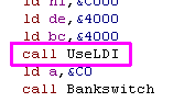 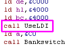 |
| Add this function to the
bottom of your code! Try the new commands, you should see they're noticeably faster! |
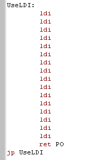 |
|
We've sped
things up but of course, the code is bigger! We've traded memory
for speed! Was it worth it? well that's depends what you can spare... This often the choice you're faced with when programming in 8 bits! |
There's not much to look at here, the only thing to note is that LDI, or LDIR set the PO flag to true when BC=0... Note, BC must be a multiple of 16, or this program will miss the 'return' and overwrite all the memory!
Stack Misuse!
There may be times when we need to read or write data super quickly... and there's a clever trick for this... as mentioned before, the Stack pointer offers the fastest reading and writing the Z80 can offer.
As we know the Stack pointer is designed for PUSH and POP, and for CALL's, but if we don't need to do any of these things, we can temporarily alter the stack pointer, and use it to bulk read, or bulk write a block of data super quick!... of course, Interrupts are a call to &0038 - so we'll have to disable interrupts to be safe! (Depending on what you're doing, you MAY be able to allow interrupts - eg if you're only writing... a few bytes would be temporarily corrupted by the interrupt handler's calls and pushes - though there are complex tricks to avoid this)
| Add "JP ClearScreen" to your jumpblock | 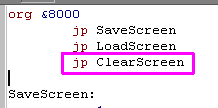 |
| Add the code to the right to
the bottom of your program There are 32 PUSH DE's in total... so get Copy-Pasting!! |
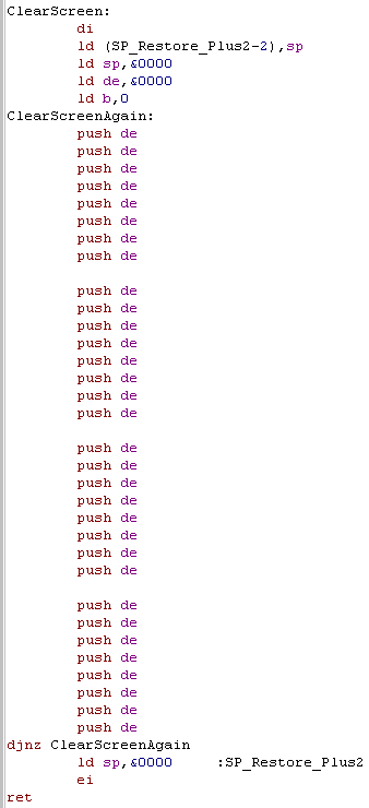 |
We've done some tricky stuff, so lets take a look!
| ClearScreen: | |
| Turn off interrupts... We're going to mess with the stack, and an Interrupt Call would use the stack, so lets stop them for safety | di |
| Back up the stack pointer using self modifying code | ld (SP_Restore_Plus2-2),sp |
| We're going to overwrite &C000-&FFFF Load the stackpointer as &FFFF+1 (&0000)... each push decreases the stackpointer by two before pushing the data, so we set the start point to the first byte to write+1 |
ld sp,&0000 |
| We're going to push DE, so this is the byte pair we're going to fill the screen with | ld de,&0000 |
| We're going to push 64 bytes each time, so we need to do this 256 times... setting B to 0 means the loop will occur 256 times before B reaches zero again | ld b,0 |
| 64 2 byte pushes | push de ... push de push de |
| Loop until B becomes zero | djnz ClearScreenAgain |
| Restore the correct stack pointer that we stored before | ld sp,&0000 :SP_Restore_Plus2 |
| Turn Interrupts back on and return | ei ret |
| ChibiAkumas
uses
Stack in this way to flood fill the background gradient super
quick... it fills the screen with a parallax gradient faster
than the firmware CLS command! It also uses POP to quickly read sprite data for transparent sprites. In fact when a game does things super fast, it's likely PUSH or POP is being misused somewhere! It's tricky though, so don't worry about it at first, get your game working with the normal stuff,then if you want you can add stack misuse later to up the frame rate! |
|
|
Congratulations!
You've reached the end of this series of lessons... We've covered all the Z80 commands you're likely to ever need, and learned lots of great stuff! But stick around! We've moving on to bigger and better things with new series' of lessons! |
This ends the Basic series.. but the lessons are just beginning!... Tune in next week for more Z80 fun!
Appendix
| Command | Alternate form | Meaning | Example | Notes |
| ADC r | ADC A,r | Add register r and the carry to A | ADC B | |
| ADC # | ADC A,# | Add number # and the carry to A | ADC 2 | |
| ADC HL,rr | Add 16 bit register rr and the carry to HL | ADC HL,BC | ||
| ADD r | ADD A,r | Adds register r to A | ADD B | |
| ADD # | ADD A,# | Adds number # to A | ADD 5 | remember ADD 254 is like -2 |
| ADD HL,rr | Add 16 bit register rr to HL | ADD HL,BC | remember ADD HL,65534 is like -2 | |
| AND r | AND A,r | bitwise AND register r with A (result in A) | AND B | |
| AND # | AND A,# | bitwise AND number # with A (result in A) | AND %11100000 | if A=%00111000... AND %11100000 will result in %00100000 |
| BIT b,r | get bit b from register r (0 is far right bit) | BIT 7,a | ||
| CALL ## | Call address ## | Call &4000 | this is like GOSUB.... Note: CALL pushes PC onto the stack | |
| CALL c,## | Call address ## if condition C is true | Call Z,&4000 | this is a THEN GOSUB statemenr | |
| CCF | Invert carry flag (compliment carry flag) | CCF | if you want to clear the carry flag, do OR A ... it will set carry flag to 0 - alternatively SCF, CCF will do the same but is slower | |
| CP r | Compare A to register r | CP A | this is your IF statement | |
| CP # | Compare A to number # | CP 255 | Use OR A instead of CP 0 - it has the same effect but is smaller and faster! | |
| CPD | Compare and decrease... CP (HL), DEC HL,DEC BC, PO set if BC=0 | CPD | ||
| CPDR | Compare and decrease, repeat ... CP (HL), DEC HL,DEC BC, until BC=0 or found | CPDR | ||
| CPI | Compare and increase... CP (HL), INC HL,DEC BC, PO set if BC=0 | CPI | ||
| CPIR | Compare and increase, repeat ... CP (HL), INC HL,DEC BC, until BC=0 or found | CPIR | ||
| CPL | invert all bits of A (ones ComPLiment) | CPL | turn %11001100 to %00110011 | |
| DAA | Special command for Binary coded Decimal, update A | DAA | ||
| DEC r | decrease value in register r by one | DEC B | ||
| DEC rr | decrease value in register rr by one | DEC HL | ||
| DI | Disable interrupts | DI | do this if you need to use shadow registers | |
| djnz # | Decrease B and Jump if NonZero... only jr jump, so must be close.. +-128 bytes away | DJNZ label | this is how you do a loop | |
| EI | Enable interrupts | EI | ||
| EX (SP),HL | Exchange the bytes at (SP) with the value in HL | EX (SP),HL | ||
| EX AF,AF' | Exchange A & Flags with the shadow register A' & Flags' | EX AF,AF' | ||
| EX DE,HL | Exchange DE with HL | EX DE,HL | HL can do more than DE, so you may want to quicly swap them | |
| EXX | Exchange BC,DE,HL with the shadow registers BC',DE',HL' | EXX | Use this if you need these register values later, but want to do another job now | |
| HALT | Wait until interrupt occurs | HALT | force music to play... DI, HALT will force emulator to stop permanently - good for debugging a particular point in the code on MSX or SPECTRUM where defining breakpoints is hard | |
| IM 0 | Interrupt mode 0 | |||
| IM 1 | Interrupt mode 1 | on the MSX or CPC this is the only one you need... on spectrum
the firmware uses this mode. on MSX... IM 1 does a CALL &0038 every screen refresh (50hz) on CPC... IM 1 does a CALL &0038 6 times during screen refresh (300hz) |
||
| IM 2 | Interrupt mode 2 | the only usable interrupt mode for our game on the ZX SPECTRUM not as easy to use as IM 1... you need to use all the memory between &8000-&8183 and the I register - but the result is the same as IM1 on the CPC/MSX |
||
| IN A,(#) | read from port # into A | IN A,(3) | Note: the Z80 on the ZX SPECTRUM & CPC are wired strangely - this function does not work right | |
| IN R,(C) | read from port C into A | in A,(C). | Note: the Z80 on the ZX SPECTRUM & CPC are wired strangely - they actually do in (B) | |
| IN (C) | read from port C... but do nothing with it | in (C). | Note: the Z80 on the ZX SPECTRUM & CPC are wired strangely - they actually do IN (B) | |
| INC r | increase r by one | INC B | ||
| INC rr | increase rr by one | INC HL | ||
| IND | In (HL),(C)...dec HL... dec B | IND | Note: the Z80 on the ZX SPECTRUM & CPC are wired strangely - they actually do in (B) which is also the loopcounter, so this will malfunction | |
| INDR | In (HL),(C)...dec HL... dec B until B=0 | INDR | Note: the Z80 on the ZX SPECTRUM & CPC are wired strangely - they actually do in (B) which is also the loopcounter, so this will malfunction | |
| INI | In (HL),(C).. Inc HL... Dec B | INI | Note: the Z80 on the ZX SPECTRUM & CPC are wired strangely - they actually do in (B) which is also the loopcounter, so this will malfunction | |
| INIR | In (HL),(C).. Inc HL... Dec B until B=0 | Note: the Z80 on the ZX SPECTRUM & CPC are wired strangely - they actually do in (B) which is also the loopcounter, so this will malfunction | ||
| JP (HL) | Jump to the address stored in HL | JP (HL) | if HL=&4000 then this would be the same as JP &4000 | |
| JP ## | Jump to ## | JP &4000 | JP is like GOTO | |
| JP c,## | Jump to ## if condition c is true | this is like a THEN GOTO statement | ||
| JR # | jump to # must be +- 128 bytes from current location | JR label | JR is faster than JP when FALSE (jump didn't occur) but slower
when TRUE (Jump occurs) JR saves one byte over JP - which is a lot on an 8 bit! |
|
| JR c,# | jump to # if condition c is true must be +- 128 bytes from current location |
JR z,label | JR is faster than JP when FALSE (jump didn't occur) but slower
when TRUE (Jump occurs) JR saves one byte over JP - which is a lot on an 8 bit! |
|
| LD (rr),A | Load memory address in (rr) with value in A | LD (BC),A | ||
| LD (##),A | Load A into memory address ## | LD (&4000),A | ||
| LD (##),rr | load 16 bit regisers rr into memory ## and ##+1 | LD (&4000),BC | bytes are loaded into memory in reverse order - though this only
matters if you're doing clever things!, eg if you do: LD BC,&1122... LD (&4000),BC &4000 = 22 &4001=11 |
|
| LD (##),SP | Load the Stack Pointer into ## | LD (&4000),SP | back up the stack pointer - you may want to use an alternate stack for a while or misuse the stack pointer for fast bulk reading or writing. | |
| LD A,(rr) | Load A from memory location (rr) | LD A,(BC) | ||
| LD A,(##) | Load A from memory location ## | LD A,(&4000) | ||
| LD A,I | Load A from the Interrupt register | The interrupt register only has a few commands, you'll need this to get data out of I | ||
| LD A,R | Load A from the Refresh register | R constantly changes - you can use it for random numbers! | ||
| LD rr,(##) | load 16 bitr registers rr from memory (##) | ld BC,(&4000) | ||
| LD I,A | Set the Interrupt register I to A | This is the only way to get data into I | ||
| LD R,A | set Refresh register to A | NEVER USE THIS - I'm told messing with the refresh register can damage your computers memory! | ||
| LD SP,(##) | Loadthe stack pointer from memory location ## | Restore the stack pointer. | ||
| LD SP,HL | Set the Stack Pointer to HL | |||
| ld r1,r2 | Load r2 into r1 | LD B,C | you can't do LD HL,BC instead do LD H,B... LD L,C |
|
| LD r,# | Load r with value # | note, rather than doing LD A,0 do XOR A... it's faster but the result is the same! | ||
| LD r,(ir+-#) | Load r from intirect register ir (IX or IY) +-# bytes | LD B,(IY+4) | IF IY=&4000 LD B,(IY+4) would do the same as LD B,(&4004) |
|
| LD rr,## | loads 16 bit number ## into rr | LD BC,&4000 | ||
| LDD | Load (DE),(HL)... DEC HL... DEC DE... DEC BC | LDD | Copy a range backwards with no repeat - faster to do this 10 times than to use LDDR with B=10 | |
| LDDR | Load (DE),(HL)... DEC HL... DEC DE... DEC BC... Repeat until B=0 | LDDR | Copy a range backwards | |
| LDI | Load (DE),(HL)... INC HL... INC DE... DEC BC | Copy a range with no repeat - faster to do this 10 times than to use LIDR with B=10 | ||
| LDIR | Load (DE),(HL)... INC HL... INC DE... DEC BC... Repeat until B=0 | Copy a range ... can also be used to fill a range by setting DE=HL+1 | ||
| NEG | NEG | Negates A... Turns 5 into -5 (251) | ||
| NOP | Does nothing | Can be used as a placeholder for self modyfying code | ||
| OR r | OR A,r | Bitwise OR r with A | OR B | |
| OR # | OR A,# | Bitwise OR # with A | OR %11100000 | if A=%00111000... OR %11100000 will result in %11111000 |
| OTDR | OUT (C),(HL)... DEC HL... DEC B... repeat until B=0 | Note: the Z80 on the ZX SPECTRUM, Sam Coupe &CPC are wired strangely - ZX & CPC actually do OUT (B),(HL)... DEC HL... DEC B.. note B is loop counter and port! this is dangerous! | ||
| OTIR | OUT (C),(HL)... INC HL... DEC B... repeat until B=0 | Note: the Z80 on the ZX SPECTRUM, Sam Coupe & CPC are wired strangely - ZX & CPC actually do OUT (B),(HL)... INC HL... DEC B.. note B is loop counter and port! this is dangerous! | ||
| OUT (#),A | OUTput A to port # (Does not work on CPC/XZ.. see notes) | Note: the Z80 on the ZX SPECTRUM, Sam Coupe & CPC are wired strangely - this command does not work | ||
| OUT (C),r | OUTput r to port C (B on CPC/XZ.. see notes) | OUT (C),C | ZX, Sam Coupe & CPC actually do OUT (B),r... this allows port and val BC to be set in one go by LD BC,nn | |
| OUT (C),0 | OUTput 0 to port C (B on CPC/XZ.. see notes) | OUT (C),0 | Note: the Z80 on the ZX SPECTRUM & CPC are wired strangely - they actually do OUT (B),0 | |
| OUTD | OUT (C),(HL)... DEC HL... DEC B | ZX, Sam Coupe & CPC actually do OUT (B),(HL)... DEC HL... DEC B.. note B is loop counter and port! | ||
| OUTI | OUT (C),(HL)... INC HL... DEC B | ZX, Sam Coupe & CPC actually do OUT (B),(HL)... INC HL... DEC B.. note B is loop counter and port! | ||
| POP rr | Pops 2 bytes off the stack and puts them in rr | POP DE | Much faster than reading DE using LD DE,(####) or LD D,(HL).. INC HL, LD E,(HL) | |
| PUSH rr | Push 2 bytes from rr into the stack | PUSH DE | Much faster than writing DE using LD (####),DE or LD (HL),D.. INC HL, LD (HL),E | |
| RES r,b | Reset bit b of register r (sets bit to zero)... Bit 0 is far right | RES B,0 | using AND # would need loading register into accumulator - this does not | |
| RET | Return | RET | return... Note: RET pops PC off the stack | |
| RET f | Return if condition f is true | RET Z | ||
| RETI | Return from Interrupt | RETI | You'll probably never need this | |
| RETN | Return from Non maskable interrupt | RETN | You'll probably never need this | |
| RL r | Rotate bits in r left using carry bit | RL B | RL A is faster than RL B | |
| RLC r | Rotate Left and Copy bit 7 to bit 0 (wrapping the bits) | RLC B | doing RLC B on %10011000 results in %00110001 | |
| RLD | Rotate Left 4 bit nibble at Destination (HL) using bits 0-3 of A as a carry | RLD | ||
| RR r | Rotate bits in register r Right with carry | RR B | RR A is faster than RR B | |
| RRC r | Rotate Right and Copy bit 0 to bit 7 (wrapping the bits) | RRC B | doing RRC B on %00001101 results in %10000110 | |
| RRD | Rotate Right 4 bit nibble at Destination (HL) using bits 0-3 of A as a carry | |||
| RST 0 | Call &0000 | RST 0 | Rst's are one byte calls, they can save memory! you cant reconfigure them on SPECTRUM | |
| RST 1-5 | Call &0008 (1), &0010 (2), &0018 (3), &0020 (4), &0028 (5) | RST 3 | ||
| RST 6 | Call &0030 | CPC defines this as spare for user configuration | ||
| RST 7 | Call &0038 | RST 7 | RST 7 is called by the Z80 when an interrupt occurs... put your own interrupt handler here to take over interrupts from the firmware! | |
| SBC r | SBC A,r | SuBtract register r and the Carry from A | SBC B | |
| SBC # | SBC A,# | SuBtract # and the Carry from A | SBC 3 | |
| SBC HL,rr | Subtract 16 bit register rr from HL with the carry | SBC HL,DE | Note there is no SUB HL,rr command - so clear the carry and use this if you need to, or use cpl to flip all the bits in each of the two regisers in rr, then do INC rr then ADD HL,rr | |
| SCF | Set the Carry Flag | |||
| SET b,r | set Bit b to 1 in register r (note bit 0 is at the far right( | Set A,0 | using OR # would need loading register into accumulator - this does not | |
| SLA r | Shift Left r and Alter bit 0 to 0 | SLA B | %01111101 becomes %11111010 | |
| SLL r | Shift Left and Load bit 0 with 1 | SLL B | %01111101 becomes %11111011 | |
| SRA r | Shift Right r and Alter bit 7 to same as previous bit 7 | SRA B | %01111101 becomes %00111110 | |
| SRL r | Shift Right and Load bit 7 with 0 | SRL B | %01111101 becomes %10111110 | |
| SUB r | SUB A,r | Subtract register r from A | SUB B | |
| SUB # | SUB A,# | Subtract number # from A | SUB 5 | |
| XOR r | XOR A,r | XOR (invert bits) in X with register r | XOR B | XOR A does the same as LD A,0 ... but is smaller and faster! |
| XOR # | XOR (invert bits) in X with number # (when bit in # is 1) | XOR %11110000 | if A=%00111000 and you do XOR %11110000 the result is %11001000 |
Note, On the CPC,Sam Coupe and ZX Spectrum due to the way the Z80 is wired OUT commands do not work as stated... OUT (C) will actually do OUT (B).. making commands like OTIR that use B as a counter likely to cause hardware problems (It caused random disk writes to me!)... OUT (#) will not work at all... OUT works normally on he MSX OUT (C) will do Out (C) and Out (#) works as stated
| View Options |
| Default Dark |
| Simple (Hide this menu) |
| Print Mode (white background) |
| Top Menu |
| ***Main Menu*** |
| Youtube channel |
| Patreon |
| Introduction to Assembly (Basics for absolute beginners) |
| Amazon Affiliate Link |
| AkuSprite Editor |
| ChibiTracker |
| Dec/Bin/Hex/Oct/Ascii Table |
| Alt Tech |
| Archive.org |
| Bitchute |
| Odysee |
| Rumble |
| DailyMotion |
| Please note: I wlll upload more content to these alt platforms based on the views they bring in |
| 68000 Content |
| ***68000 Tutorial List*** |
Learn 68000 Assembly  |
| Hello World Series |
| Platform Specific Series |
| Simple Samples |
| Grime 68000 |
| 68000 Downloads |
| 68000 Cheatsheet |
| Sources.7z |
| DevTools kit |
| 68000 Platforms |
| Amiga 500 |
| Atari ST |
| Neo Geo |
| Sega Genesis / Mega Drive |
| Sinclair QL |
| X68000 (Sharp x68k) |
| 8086 Content |
| Learn 8086 Assembly |
| Platform Specific Series |
| Hello World Series |
| Simple Samples |
| 8086 Downloads |
| 8086 Cheatsheet |
| Sources.7z |
| DevTools kit |
| 8086 Platforms |
| Wonderswan |
| MsDos |
| ARM Content |
| Learn ARM Assembly |
| Learn ARM Thumb Assembly |
| Platform Specific Series |
| Hello World |
| Simple Samples |
| ARM Downloads |
| ARM Cheatsheet |
| Sources.7z |
| DevTools kit |
| ARM Platforms |
| Gameboy Advance |
| Nintendo DS |
| Risc Os |
| Risc-V Content |
| Learn Risc-V Assembly |
| Risc-V Downloads |
| Risc-V Cheatsheet |
| Sources.7z |
| DevTools kit |
| MIPS Content |
| Learn Risc-V Assembly |
| Platform Specific Series |
| Hello World |
| Simple Samples |
| MIPS Downloads |
| MIPS Cheatsheet |
| Sources.7z |
| DevTools kit |
| MIPS Platforms |
| Playstation |
| N64 |
| PDP-11 Content |
| Learn PDP-11 Assembly |
| Platform Specific Series |
| Simple Samples |
| PDP-11 Downloads |
| PDP-11 Cheatsheet |
| Sources.7z |
| DevTools kit |
| PDP-11 Platforms |
| PDP-11 |
| UKNC |
| TMS9900 Content |
| Learn TMS9900 Assembly |
| Platform Specific Series |
| Hello World |
| TMS9900 Downloads |
| TMS9900 Cheatsheet |
| Sources.7z |
| DevTools kit |
| TMS9900 Platforms |
| Ti 99 |
| 6809 Content |
| Learn 6809 Assembly |
| Learn 6309 Assembly |
| Platform Specific Series |
| Hello World Series |
| Simple Samples |
| 6809 Downloads |
| 6809/6309 Cheatsheet |
| Sources.7z |
| DevTools kit |
| 6809 Platforms |
| Dragon 32/Tandy Coco |
| Fujitsu FM7 |
| TRS-80 Coco 3 |
| Vectrex |
| 65816 Content |
| Learn 65816 Assembly |
| Hello World |
| Simple Samples |
| 65816 Downloads |
| 65816 Cheatsheet |
| Sources.7z |
| DevTools kit |
| 65816 Platforms |
| SNES |
| eZ80 Content |
| Learn eZ80 Assembly |
| Platform Specific Series |
| eZ80 Downloads |
| eZ80 Cheatsheet |
| Sources.7z |
| DevTools kit |
| eZ80 Platforms |
| Ti84 PCE |
| IBM370 Content |
| Learn IBM370 Assembly |
| Simple Samples |
| IBM370 Downloads |
| IBM370 Cheatsheet |
| Sources.7z |
| DevTools kit |
| Super-H Content |
| Learn SH2 Assembly |
| Hello World Series |
| Simple Samples |
| SH2 Downloads |
| SH2 Cheatsheet |
| Sources.7z |
| DevTools kit |
| SH2 Platforms |
| 32x |
| Saturn |
| PowerPC Content |
| Learn PowerPC Assembly |
| Hello World Series |
| Simple Samples |
| PowerPC Downloads |
| PowerPC Cheatsheet |
| Sources.7z |
| DevTools kit |
| PowerPC Platforms |
| Gamecube |
| Work in Progress |
| ChibiAndroids |
| Misc bits |
| Ruby programming |
Buy my Assembly programming book
on Amazon in Print or Kindle!


Available worldwide!
Search 'ChibiAkumas' on
your local Amazon website!
Click here for more info!


Buy my Assembly programming book
on Amazon in Print or Kindle!
Available worldwide!
Search 'ChibiAkumas' on
your local Amazon website!
Click here for more info!
Buy my Assembly programming book
on Amazon in Print or Kindle!
Available worldwide!
Search 'ChibiAkumas' on
your local Amazon website!
Click here for more info!
Buy my Assembly programming book
on Amazon in Print or Kindle!
Available worldwide!
Search 'ChibiAkumas' on
your local Amazon website!
Click here for more info!
Buy my Assembly programming book
on Amazon in Print or Kindle!
Available worldwide!
Search 'ChibiAkumas' on
your local Amazon website!
Click here for more info!
Buy my Assembly programming book
on Amazon in Print or Kindle!
Available worldwide!
Search 'ChibiAkumas' on
your local Amazon website!
Click here for more info!
Buy my Assembly programming book
on Amazon in Print or Kindle!
Available worldwide!
Search 'ChibiAkumas' on
your local Amazon website!
Click here for more info!
Buy my Assembly programming book
on Amazon in Print or Kindle!
Available worldwide!
Search 'ChibiAkumas' on
your local Amazon website!
Click here for more info!
Buy my Assembly programming book
on Amazon in Print or Kindle!
Available worldwide!
Search 'ChibiAkumas' on
your local Amazon website!
Click here for more info!
Buy my Assembly programming book
on Amazon in Print or Kindle!
Available worldwide!
Search 'ChibiAkumas' on
your local Amazon website!
Click here for more info!
Buy my Assembly programming book
on Amazon in Print or Kindle!
Available worldwide!
Search 'ChibiAkumas' on
your local Amazon website!
Click here for more info!